Output to Reame creates a file with a .dat extension that is readable by the REAME2004 stability analysis program for cylindrical failure. The REAME program was developed by Dr. Huang of the University of Kentucky and is widely used in coal mine permitting in the state of Kentucky. The linkage has been tested and verified with the REAME2004.
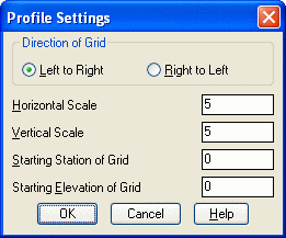
The program is typically used after a final surface profile is laid graphically over an existing ground profile. You then graphically select the profiles to create the REAME input file. The routine not only creates the input file but provides options to draw the failure study region and key coordinates on the actual profile drawing. The only significant condition to be aware of is that the profiles should rise upwards from left to right in the direction of increasing station.
To run the Reame program after Output to Reame, it is best to copy the .dat file just made into the directory containing REAME.EXE. Then run REAMEINP to revise the .dat file (to change aspect like cohesion, friction angle and unit weight) or REAME to run the stability analysis. It will ask: FILE NAME -? Enter the name with the .dat extension included. The enter 1 to input from file. The analysis is then completed and stored in a file REAME.TXT.
[end on]Pick Lower Left Grid
Corner <0.00,1445.00>: pick where the
starting station and starting elevation grid lines intersect
Switch to int snap if that point is not an end point.
Select Final Grade
Polyline: pick final grade
Select Lowest Surface
Polyline: pick existing grade Phantom lines at
right angles representing the proposed study area for stability
analysis now appear.
Pick another Surface
(y/<n>): n, Yes for
adding more surface polylines to reame input
Minimum Depth (DMIN) for Failure
Slice:
Lowest Surface:
Value for C <0>:
Value for Phid
<40>:
Value for G
<125>:
Note: Lines will not Appear at
Right Angles if Vert. Scale is Exaggerated.
Translated Coords: (-10.0 68.9902) (515.0 173.99)
Is Stability Analysis Zone
Acceptable (<y>/n):
Plot Stability Analysis Zone Lines
(<y>/n):
Label the Zone Line Endpoints
(<y>/n):
[end on] Pick Points for Coord.
Label (enter to continue): pick any ground line or final grade
line vertices or endpoints for coordinate labeling Each time
you will also be asked:
[none] Pick Starting Point for
Text: pick a point
[end on] Pick Points for Coord.
Label (enter to continue):
[none] Pick Starting Point for
Text:
[end on] Pick Points for Coord.
Label (enter to continue):
[none] Pick Starting Point for
Text:
[end on] Pick Points for Coord.
Label (enter to continue):
Number of divisions along face of
slope <4>:
Number of divisions perpendicular
to slope <8>:
This would lead to 32 radius points
from which to test cylindrical failure.
Pulldown Menu Location: Surface > Slope Stability
Keyboard Command: reame
Prerequisite: Surface profiles or polylines