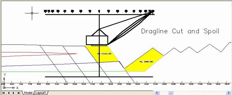
This command removes a cut area in cross-section view from a surface polyline and places a spoil pile of this area. Before starting this command, the surface should be drawn as a polyline from left to right. One way to draw the polylines is to use the Fence Diagram routine. In Fence Diagram use the option to draw the polylines as single polylines instead of closed polylines (with no hatching). Also, if there is an existing pit, turn on Draw Surface Polyline to make sure the surface line extends across the pit floor. The Draw Dragline Limits command can optionally be run before Cut & Place to draw an outline of the maximum reach, height and depth of the dragline.
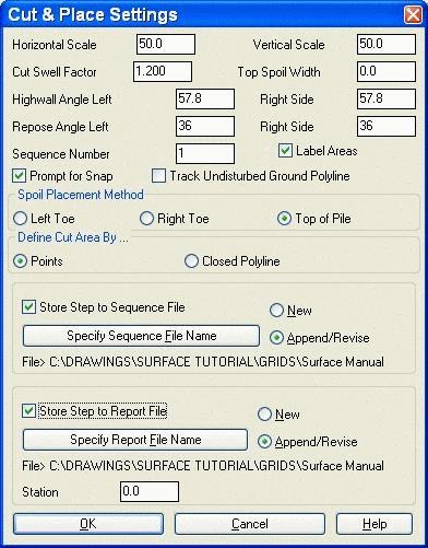
Cut & Place first brings up a dialog for setting the scale. The Horizontal Scale and Vertical Scale are used to determine the vertical exaggeration of the cross-section view. The Cut Swell Factor will be applied to any new cut areas. The Cut Volume Swell Factor is multiplied by the cut area to determine the fill area of the spoil pile. The Top Spoil Width is the flat width at the peak of the spoil pile in feet or meters. The Highwall Angle is used with the Define Cut Area By Points option as the angle from the picked points at the bottom of the cut area up to the surface. There are both left and right windows. The Repose Angle is the angle of the spoil pile. This can vary, as shown later in an extended bench example. All four of the Angles should be entered in as degrees. The Label Areas option will draw text for the cut and fill amounts, prompting you to pick the text locations. Prompt for Snap activates a snap dialog box during the picking phase of the routine. Track Undisturbed Ground Polyline should be turned on to track rehandle, to make sure it is not swollen more than once, and for reporting rehandle quantities. The Sequence Number window is for entering in the step number for the sequence file if the Store Step to Sequence File is being written. The Spoil Placement Method allows for selecting the position of the Left Toe, Right Toe, or the Top of Pile. These locations will be constant when processing the sequence. The Define Cut Area is either by Points, where you select the lower left, then the lower right cut points, or by a pre-drawn closed polyline representing the cut block.
The Store Step to Sequence File will write out a SEQ file for later processing with Process Dragline Sequence. This file should be set to New for step number 1, then set Append/Revise for any further steps from 2 or more. This method will take the one range diagram template and apply it to the entire pit along a centerline. The Store Step to Report File is used if the user is running cut and place on multiple cross-sections. The file should be new for the first Station, then set to Append/Revise for additional stations. These are processed with the Dragline Section Report commands.
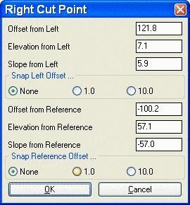
When picking points, there is an option to select a strata polyline which will be used as the bottom cutoff for the cut area. Also while picking the points, there is a real-time window that shows the point offset, slope and distance as you move the cursor. Once the point is picked a snap dialog allows you to adjust the picked point. For example, you could use the real-time window to visually pick the right cut point. The actual picked right position could be 201.32 from the left point and then you can the snap dialog to round the position to 200. This adjust point dialog only appears if the Prompt for Snap option is on. You can also specify a reference point by typing 'R' for the Reference option at the command prompt. This option will prompt you to pick a reference point in the section. For example you could choose the toe of the existing highwall as the reference point and make the right cut point offset by 10.0.

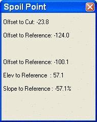
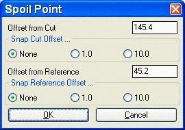
After choosing the cut area, the spoil pile is placed by picking a point to place the spoil. This point can be either the left toe of slope, right toe of slope or top of pile. After defining the cut and spoil, there is an option to go back and adjust the cut or spoil points. Select L, R or S for left point, right point or spoil location. Adjusting the cut points will automatically resize the spoil pile-watch it dynamically change. Once everything is set, press Enter to end the routine. The surface profile polyline is redrawn with the cut area removed and the spoil added. The changed segments of the original surface are drawn a different color, usually gray.
The user input for this command can be saved to a sequence file (.SEQ) for the Process Dragline command or a section report file (.CUT) for the Dragline Section Report command. With the sequence file active, the program will prompt for a centerline reference point which is the point in the cross-section view that the centerline for Process Dragline passes through. It needs this point to locate the cross-section horizontally in the plan view relative to the centerline drawn in plan view. If you choose a strata polyline, the program will ask for the strata name of this polyline. The Process Dragline command will then prompt for a grid file that models this strata name. The data that is saved includes the depth and offset of the cut points, the spoil pile offset, and the slopes. Besides specifying the sequence file name to write to, the sequence number is also stored. This number orders the steps in Process Dragline. For the Dragline Section Report, the program will store the station, sequence number, and cut and fill areas.
The Track Undisturbed Ground Polyline option is for calculating rehandle. With this option on, the program will prompt for the existing ground polyline as usual plus an additional undisturbed ground polyline. The undisturbed polyline is the same as the existing ground polyline except that the undisturbed polyline does not have the spoil piles. One way to start this process is just copy the Surface line onto itself, then move one away from the other on one of the ends for ease of selecting for the first cut. After the first cut, it should be easy to select one or the other. Cut & Place will update the undisturbed polyline by removing the cut area and will not add the spoil pile. The program will also report any rehandle using the undisturbed polyline. The swell factor is not applied to the rehandle.
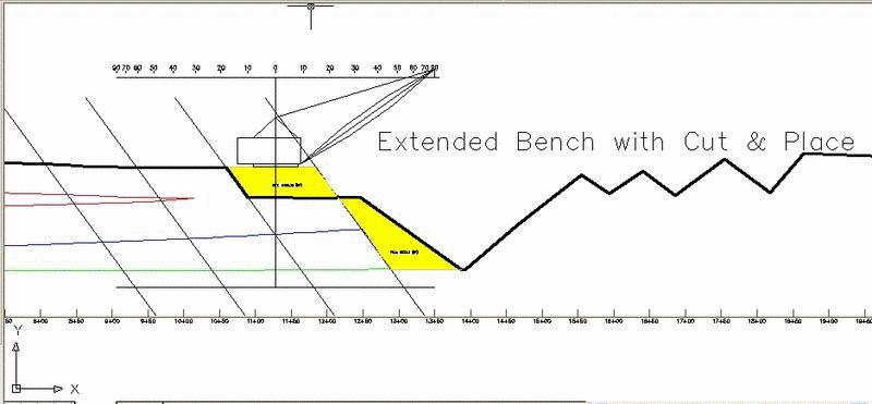
This command will also fill in for some of the Dozer Push short
comings. If the is a simple extended bench needed, the set one of
the spoil slopes to 0 and it will create a flat spoil for that
step. Be sure to hit enter when prompted for the top of coal line.
The next cut could be a pre-drawn, closed polyline or a series of
cuts to remove the material. The lower right cut slope in the case
could be the same as the spoil slope to create the left slope of
the spoil.
Cut & Place Settings Dialogs
Select existing ground polyline: pick a polyline
Pick centerline reference point on ground polyline: pick
a point on ground polyline
Select strata polyline (Enter for none): pick the strata
polyline
Enter strata name for strata polyline: UB_TOP
Reference/<Pick lower Left cut point>: pick a
point
Reference/<Pick lower Right cut point>: pick a
point
Right Cut Point dialog
Reference/<Pick spoil pile location>: pick a
point
Control point to adjust (Left cut/Right
cut/Spoil/<None>)? press Enter
CUT: 2327.00 (sf) FILL: 2327.00 (sf)
Pulldown Menu Location: Surface
Keyboard Command: range1
Prerequisite: Surface polyline in profile view from a
Profile or Fence Diagram. Grids of the seams if writing sequence
file.