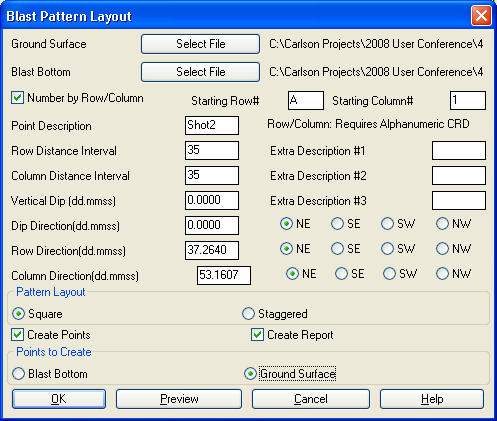
This command creates a pattern of points in rows and columns
using surface and shot bottom grids and dip direction. The options
for this command are set in the dialog. Grid files for the ground
surface and drill bottom are required. The Number By Row/Column
option will number the holes by the hole row and column. Otherwise
the holes are simply numbered sequentially. Up to four descriptions
can be assigned to the holes such as pattern name, driller name,
etc. The row and column distances can be specified separately. The
drilling angle can be set in the Vertical Dip field which is
entered as an angle where 0 degrees is straight down and 90 degrees
is horizontal. The Dip Direction defines the horizontal orientation
of the vertical dip. The row and column directions are entered as
bearing angles. You need to figure these angles before running
Blast Pattern Layout by using routines such as Inverse or Bearing
& 3D Distance. The format is in dd.mmss where the
degrees.minutesseconds are separated by a decimal.
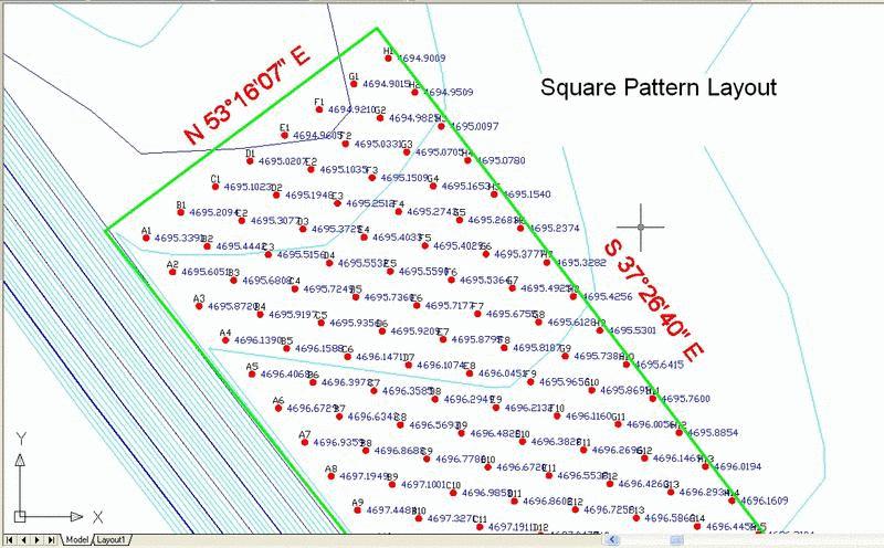
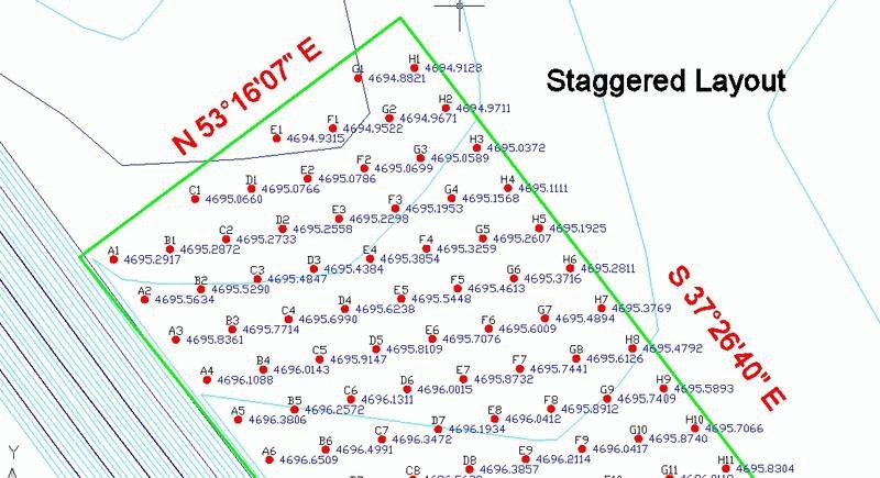
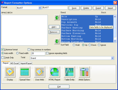
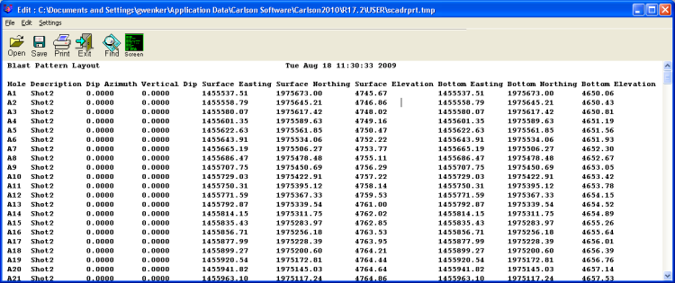
This command can generate a report using the report formatter that lets you choose the fields for the report and the fields layout. The report formatter can also output to Excel and Access. The points can be also be stored to the current coordinate file (.crd). The Preview button shows a preview of the pattern in the drawing so that if something isn't right, it can be adjusted before choosing OK. If the Create Points is turned on, then the points will be drawn in the blast perimeter. Use the Create Lines option to draw 3D lines for each blast hole on the specified layer.
After filling out the dialog, the program prompts for the blast boundary polyline which should be a closed polyline of the blast area. Finally you specify the starting point within this boundary polyline and the program calculates the points.
Blast Pattern dialog
Select blast boundary polyline: pick a polyline
Pick starting point: pick a point
Pulldown Menu Location: Surface
Keyboard Command: blast2
Prerequisite: Surface and pit grids