This command gives a 3D approach to the design and placement of dragline pits. Unless all the seams are perfectly uniform and horizontal, and pits are straight, the usual cross-section dragline modeling with range diagrams will not provide the appropriate level of precision and visualization. This function allows you to specify the cut and spoil areas and watch the ground surface change in 3D. Surface updates are recorded on every step and may be played back later.
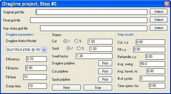
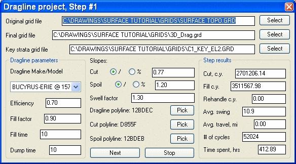
The first step is to define the three grid files at the top of the Dragline project window. They are the original topo grid file, the final grid file (create a new grid if one doesn't exist) and the top of the Key strata grid file.
The Dragline parameters section is for choosing the dragline. Then set its Efficiency %, Fill Factor %, Fill time (seconds) and Dump time (seconds). The Slope and Swell factor are set next, in the center of the screen. Slope is either set as ratio or percentage. A swell factor of 1.3 gives 30% swell.
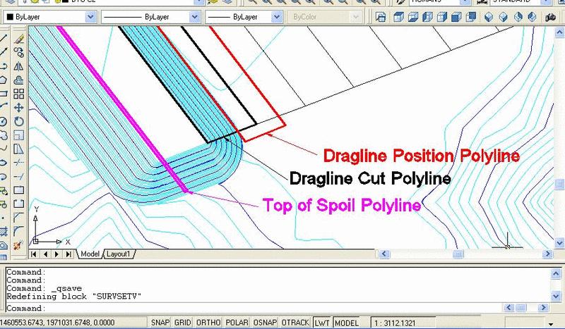
Finally, on each step of the sequence, three pre-drawn closed polylines are chosen: a polyline enclosing the area within which dragline is allowed to move, a bottom of cut area polyline (usually the next pit line), and a top of spoil area polyline (usually the previous pit line). The program then offsets the dragline polyline by the maximum reach distance and crops out the portions of cut and spoil polylines within the dragline reach. These modified polylines will be used in calculations. This allows the program to use larger cut and spoil polylines and move only the dragline on each step.
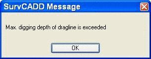
The program then calculates the overburden volume by using surface grid on top, coal top grid on bottom, and the highwall calculated using the cut polyline and given cut slope. The cut polyline is projected onto the bottom grid prior to calculations. The swell factor is then applied to the freshly cut material, while the rehandled material amount is taken as is. If the spoil polyline is a 3D polyline, its profile will be the elevations of the polyline. Otherwise the spoil ridge is considered to be at the same elevation. The spoil polyline is then moved up and down until the amount of the material between the spoil pile and the existing surface matches the given amount. If any dragline parameters are too small to physically mine here, then error messages, are displayed accordingly.
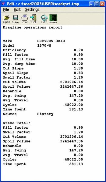
The calculated cut, spoil, rehandle and timing results are then displayed in the dialog. You may then modify the selection of cut, spoil or dragline polylines and proceed to the next step, or use the Stop button to exit. With use of the history file, the scheduling may be restarted from the point it was finished. Surfaces are updated with each step. To get to the next step, simply select then next 3 polylines, change the first two grid names (the top of coal usually remains the same) and choose next. After each step, the report formatter appears, allowing for customized reports of the steps.
|
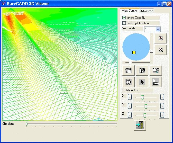
| 3D View of the first step The grid has been colored by elevation to show the ranges better. |
Create or choose the DHT
file. (Dragline history file.)
Dragline project dialog
Pulldown Menu Location: Surface
Keyboard Command: cut_n_drop