This next tutorial shows how to run Surface Equipment Timing through a series of benches in pits. This example starts with a pit layout mineplan and structure grids. It is assumed that you already know those operations. Then Design Bench Pit is run on the pits, creating output grids and a Grid Sequence File. Next the quantities for each bench will be calculated and stored in the pit polylines. Then the sequence of mining the benches and pits is assigned and run with Surface Equipment Timing.
Creating Pit Polylines
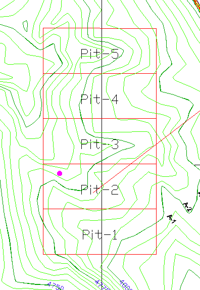
The first step is to sub-divide the overall pit perimeter into
smaller pits. In this example, the larger rectangular mine
perimeter is subdivided into 5 smaller pits, named Pit-1 through
Pit-5. These will be draped onto the bottom of the pit and benches
will go up and out from them. The command Pit Layout By Advance was
used to lay them out.
Assigning Pit Directions
In order to schedule the equipment through the pits, the direction
of mining needs to be assigned to each pit. In this case, the
direction of mining for each pit will be from left to right. First
draw a direction polyline through the pits from bottom to top. Then
run the Assign Directions command and use the Sequence method with
the LL option.
Assign direction using which method (<Auto>, Text,
Sequence, Polyline): S for Sequence
Select pit polylines to have direction assigned to:
Select objects: select the pit polylines
Select a direction polyline: pick the direction
polyline
Assign direction in which sequence (<LL>, LR, RL, RR):
LL
The pits now have direction assigned from west to east.
Design Bench
Pit
Using the pit perimeters as the inclusion areas, the program will
draw the 3D pit shells, output grids and calculate volumes for each
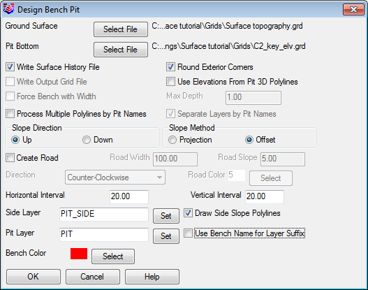
pit and bench. Before running Design Bench Pit, you need the pit
bottom perimeter polylines and grid files for the ground surface
and benches. In the first dialog, specify the ground surface grid
and the bottom elevation grid for the last bench. Also be sure the
Process Multiple Polylines by Pit Names and Write Surface History.
A grid file for each pit and each bench is created, and they are
automatically organized in the Grid History File (GSQ).
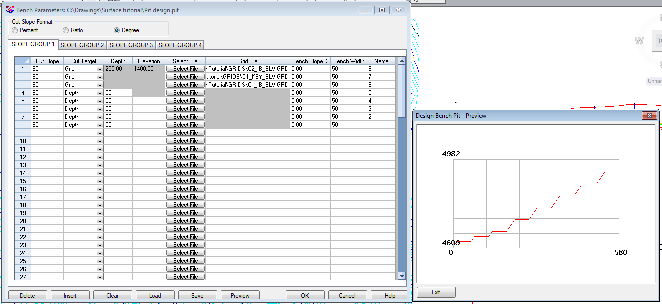
In the next dialog, you specify the side and bench slopes. The height of the side slopes can be specified by either a depth number or a grid file. In this case we will use grid files as well as by depth. Four different sets of slopes can be applied to different sides of the pit. For this example, the same slopes will be used on all sides. You can use up to 100 benches.
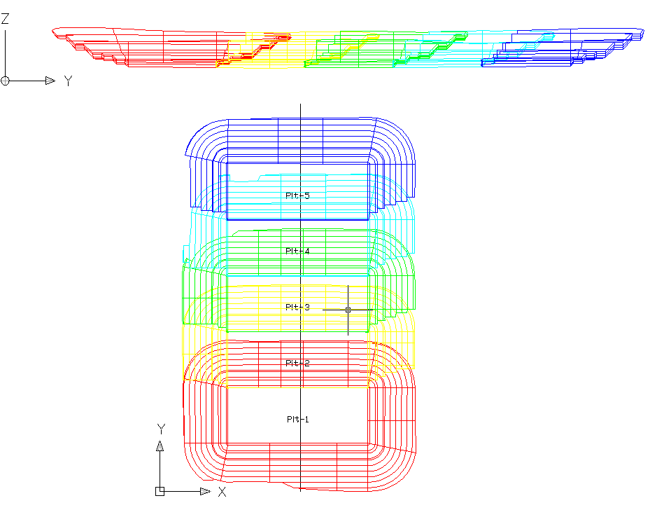
 The output will look as such. Each pit is
in its own layer and colored differently. In the above view, the
pits are laid down on the side, to show the slope to each
grid.
The output will look as such. Each pit is
in its own layer and colored differently. In the above view, the
pits are laid down on the side, to show the slope to each
grid.
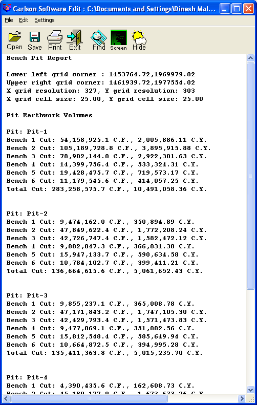
 Each pit and bench quantity is reported in
the basic text report.
Each pit and bench quantity is reported in
the basic text report.
Assigning Bench Quantities
The next step is to store quantities in each pit for each bench
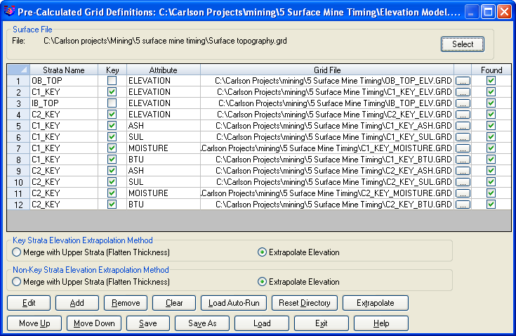
using the Surface Mine Reserves command. Before running this
command, you need to have a Pre-Calc Grid file (.PRE) in addition
to the GSQ history file. This is what determines the bench
quantities and automatically assigns them to the benches.. Use the
Define Pre-Calc Grids command to specify the grids as shown
below.
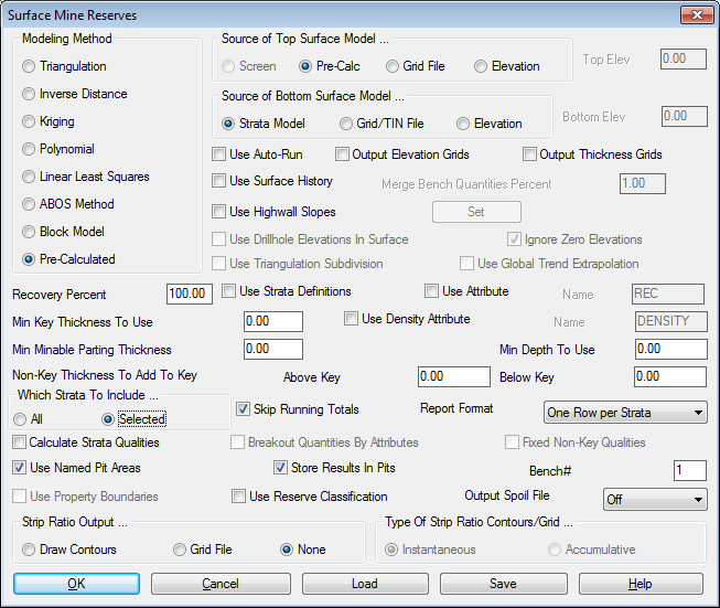
Then run Surface Mine Reserves. The dialog shown below appears.
Set the modeling method to Pre-Calculated and you can leave it set
to Bench 1. Since we are using the GSQ file, all five benches will
be assigned automatically. Turn on all the options you see
here.

Some important items to make sure are selected are Use Surface
History, Use Named Pit Areas, and Store Results in Pits. After
clicking OK on the dialog, specify the Pre-Calc file shown above.
Next the program prompts for the Grid History File created earlier
by the Design Bench Pit routine. The Merge Bench Quantities Percent
applies here. If there is some grid "bleeding" where one seam
bleeds into another bench due to the grid cell size, then this
option will put that material back into the correct bench, as long
as the amount is not less than this percentage.
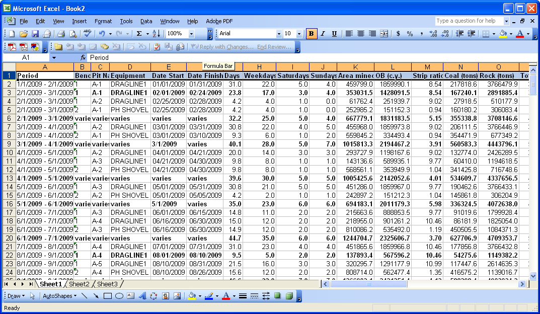
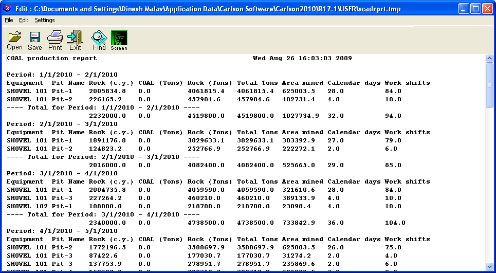
Now the program will calculate the quantities of all the benches for all the pits. A report formatter allows you to optionally print or display the results. The quantities are stored in the pit polylines for scheduling. If you are not using the GSQ file, then you will have to run this for each bench number, with all the same options except set the Bench # to 2 and choose only Bench 2 from the strata list (Selected Strata turned on). Then repeat this command a third time using bench 3 etc. That is what is nice about the GSQ file, it does them all at once, even calculating and assigning the layback slope volume accordingly. Shown next is the pit by pit and bench by bench volume report.
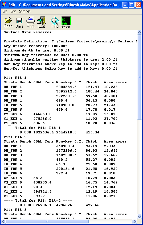
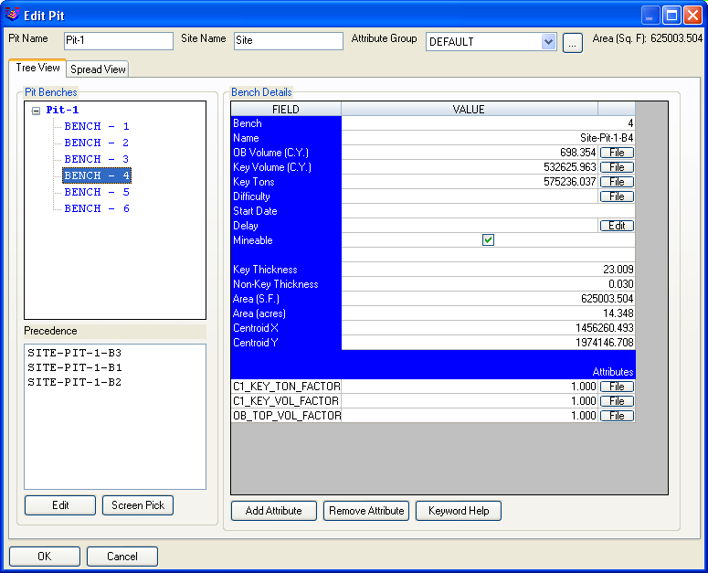
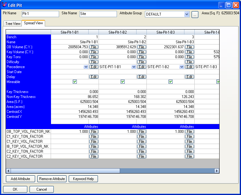
These values are now stored in the pits and can be verified with
Edit Pit under Boundary. Click inside any one of the pits to see
the values. All benches can be accessed by selecting the bench
number in the tree view on the left of the dialog or by selecting
the Spread View tab to view data for all benched at a time.
Surface Project Manager
The Surface Project
Manager can be accessed under Reserves/Timing dropdown menu. It
allows user to define Equipments, Timing Calendar, Pit Attributes
as well as other essential parameters to be used in the
timing.
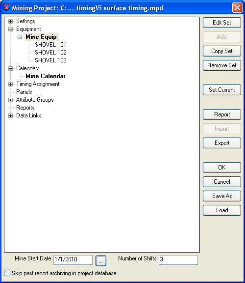
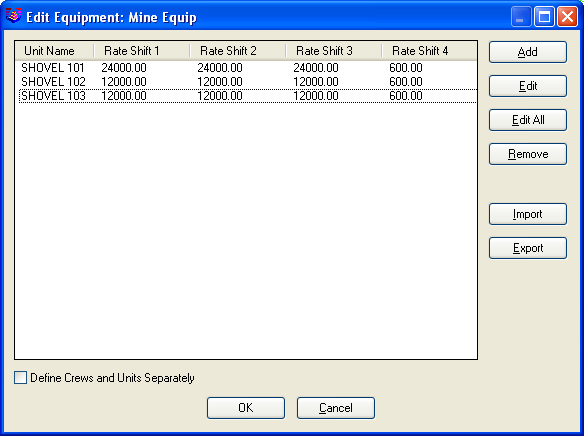
Define Equipment
Select the Edit Set in Project Manager to create an equipment
definition to mine the pits. This example will use three shovels.
This command shows a list of existing equipment definitions. Choose
the Add button and fill out the dialog as shown below for a three
shift operation for all shovels. Shovel1 mines 24000 CY/shift and
Shovel 2 and Shovel3 mines 12000 CY/Shift.

Define Calendar
The next step is to define the calendar. By default, both units are
working every day, every shift. It is your job to take off
holidays, weekends and maintenance down time.

Surface Equipment Timing
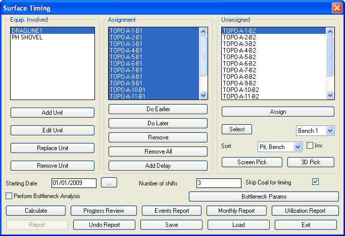
The Surface Equipment Timing command schedules the equipment
through the pits. The first dialog shows three list boxes for the
equipment, the pits assigned to the equipment and the unassigned
pits. The pit benches are listed as site name - pit name - bench
number. For example, "Site 1-Pit 1-2" is for bench 2 in pit1. To
set the equipment to use, choose the Add Equip button and select
the equipment name defined in the last step.

The sequence of mining the pit benches must be assigned. In this case, we want a 5-step staircase that advances through the pits. By default the pit benches are sorted in the unassigned list by pit number then bench number. To arrange the pit benches in the staircase order, choose the Sort dropdown list and select 5-Bench Staircase. Then pick the Select button followed by the Assign button. This will assign the pit benches to the equipment in staircase order. In this example, just manually select the first pit/bench, and holding the CTRL button down, select every other one. Then hit Assign, assigning them to Shovel1. Then highlight Shovel2, hit Select All, and assign the remaining pits/benches to Shovel2.
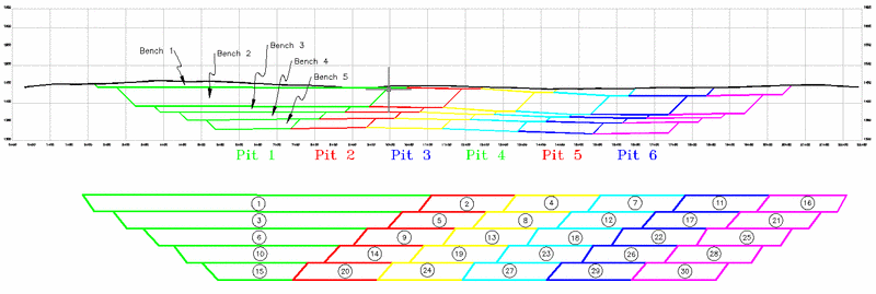
Shown above are 6 profiles of the bench pits. They have been manually connected with polylines and the pits and benches are labeled to show the "blocks". This is to illustrate the real bench width in cross section view. The lower graphic shows this profile exaggerated and numbered exactly as each block is going to be sequenced in the 5 bench staircase method. The sequencer automatically sorts them in this order.
The 3D Pick option can be used to graphically select each bench and pit in the order to be mined. It is very useful for short-term scheduling. Just select 3D Pick, rotate it to an useful 3D view and then double click on each block. It will be removed and assigned to the highlighted unit.

When all the pit benches are assigned as shown in the dialog, click the Calculate button. The program will then run the equipment through the pits and report the completion date. Then click the Detailed Report button. This brings up the Report Options button.
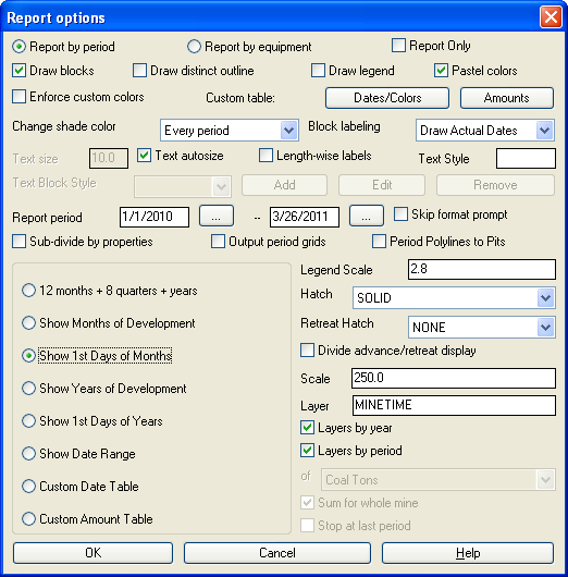
In this case, the report period is set to Show 1st Days of Months. This will give a monthly schedule from the first of each month. Following is a report by monthly period. This can be formatted in many ways and exported to Excel.
Multi-Bench Mining Example Setup:
The defining of equipment, crews and equipment calendar are
(potentially) one-time operations. Similarly, the making of the
Geologic Model needs be done only once in advance of numerous
timing runs. Surface Equipment Timing, also distinct from Surface
Production Timing, allows multi-bench mining by use of different
equipment or the same equipment mining different benches, with
different production rates. Since single-bench mining is a subset
of multi-bench mining, this will illustrate the command with a
multi-bench example. Surface Mine Reserves is one of three methods
to place quantity and quality information into the pits, by bench.
This example will use Surface Mine Reserves. If there are two
benches, Surface Mine Reserves must be run twice, one time
for each bench. The dialog within Surface Mine Reserves should be
completed as follows for Bench 1:
 The
key is to choose "Selected" strata (for benching) as well as "Use
Named Pit Areas" and "Store Results in Pits". You should also
select "Calculate Strata Qualities" to assign quality information
to the pits. If single-bench mining is conducted, you may omit the
"Selected" option. Other items in the dialog are set according to
user preference. Note the option "Output Thickness Grids". If this
is not selected, total quantity and composited quality information
is placed in the pits, and mining across a single pit is
proportional. However, if the "Make Thickness Grids" option is
selected, mining across the pits picks up the varying of the
overburden thickness, coal thickness and quality information. For
small pits or "blocks" as they are sometimes called, storage of
total information will still lead to reliable results. Thickness
grids are recommended for large and long pits, where the thickness
will vary. The choice of "Selected" strata requires that the user
select which strata will be mined in Bench 1. The following Choose
Strata dialog at will appear:
The
key is to choose "Selected" strata (for benching) as well as "Use
Named Pit Areas" and "Store Results in Pits". You should also
select "Calculate Strata Qualities" to assign quality information
to the pits. If single-bench mining is conducted, you may omit the
"Selected" option. Other items in the dialog are set according to
user preference. Note the option "Output Thickness Grids". If this
is not selected, total quantity and composited quality information
is placed in the pits, and mining across a single pit is
proportional. However, if the "Make Thickness Grids" option is
selected, mining across the pits picks up the varying of the
overburden thickness, coal thickness and quality information. For
small pits or "blocks" as they are sometimes called, storage of
total information will still lead to reliable results. Thickness
grids are recommended for large and long pits, where the thickness
will vary. The choice of "Selected" strata requires that the user
select which strata will be mined in Bench 1. The following Choose
Strata dialog at will appear: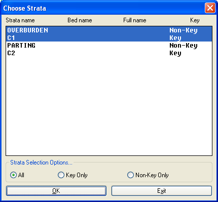 Holding the CTRL or SHIFT key down, will select Overburden
and C1 to mine down to the bottom of the first coal (C1). Bench 2
would be comprised of Parting and C2. Following two runs of Surface
Mine Reserves, new information has been added to the pits. Pits
contain up to three categories of information: pit name (verified
by using "Identify Pit Polylines"), pit direction and pit
quantities/qualities organized by bench. Pit quantities and
qualities are needed only for Surface Equipment Timing, and can be
verified using the command "Edit Pit". For example, the information
in Edit Pit is shown below. Select the "Attribute" option to reveal
the quality attributes.
Holding the CTRL or SHIFT key down, will select Overburden
and C1 to mine down to the bottom of the first coal (C1). Bench 2
would be comprised of Parting and C2. Following two runs of Surface
Mine Reserves, new information has been added to the pits. Pits
contain up to three categories of information: pit name (verified
by using "Identify Pit Polylines"), pit direction and pit
quantities/qualities organized by bench. Pit quantities and
qualities are needed only for Surface Equipment Timing, and can be
verified using the command "Edit Pit". For example, the information
in Edit Pit is shown below. Select the "Attribute" option to reveal
the quality attributes.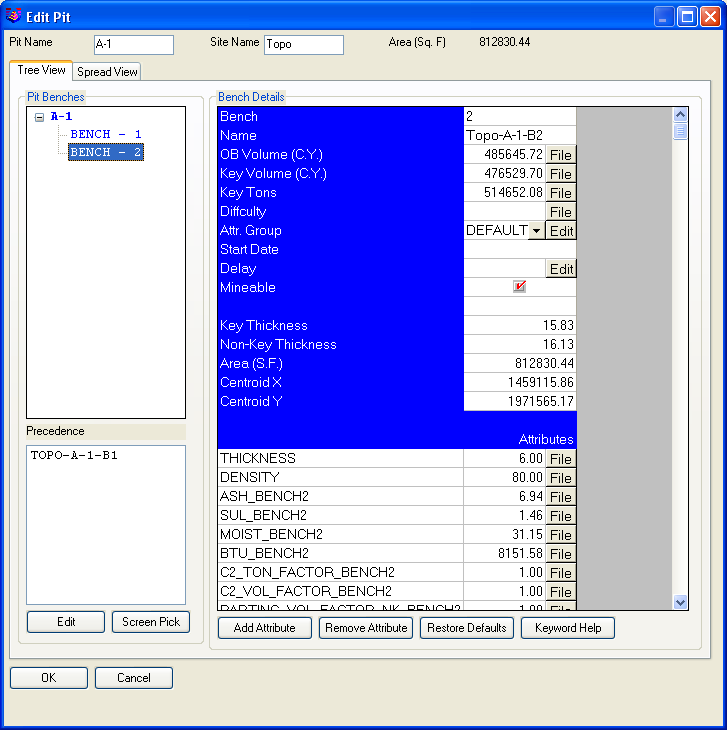

 It is also
important to note the option "Skip Coal for timing" at the lower
right of the dialog box. Here you can base all progress on the
NonKey overburden and parting only, on the assumption that the
loaders or other equipment digging the coal will "keep pace" with
the equipment removing the overburden and interburden. If "Skip
Coal for timing" is not selected, the coal volume will be included
in the total quantity mined by the equipment. We can add a second
piece of equipment, then highlight it within the Surface Timing
dialog and assign all the remaining pits to it (Select All or Bench
2, then Assign). Note also that we can add a delay between
completing the Bench 1 pit and beginning the Bench 2 pit. Delays
are automatically inserted below the highlighted pit, so if a pit
is highlighted, a delay will be added below it that can be moved up
or down also. There is a prompt to add this as a calendar or
schedule delay (described above). Shown below is the
assignment for Bench2.
It is also
important to note the option "Skip Coal for timing" at the lower
right of the dialog box. Here you can base all progress on the
NonKey overburden and parting only, on the assumption that the
loaders or other equipment digging the coal will "keep pace" with
the equipment removing the overburden and interburden. If "Skip
Coal for timing" is not selected, the coal volume will be included
in the total quantity mined by the equipment. We can add a second
piece of equipment, then highlight it within the Surface Timing
dialog and assign all the remaining pits to it (Select All or Bench
2, then Assign). Note also that we can add a delay between
completing the Bench 1 pit and beginning the Bench 2 pit. Delays
are automatically inserted below the highlighted pit, so if a pit
is highlighted, a delay will be added below it that can be moved up
or down also. There is a prompt to add this as a calendar or
schedule delay (described above). Shown below is the
assignment for Bench2.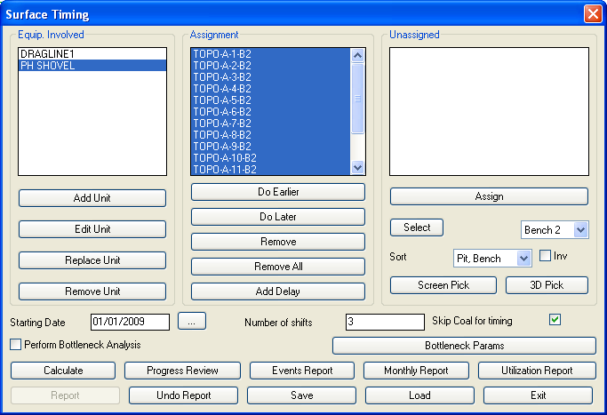 To complete
the calculation, fill in the Starting Date (if the default is not
correct), then click on Calculate. This leads to a completion date
and the option of a unit report or going directly to the Report
Options screen. The Unit Report is very instructive because it
highlights when equipment has been idled. Our Bench2 dragline is
waiting each time for the "slower" Bench1 dragline to complete
bench 1 before it can launch into bench 2. The planner could try
lower rated equipment, or reverse the assignments of the equipment,
or simply re-shuffle the assignments in any desired manner to
maximize efficiency. The last step is to choose "Report" when
returned to the Surface Timing dialog which brings up the Report
Options dialog.
To complete
the calculation, fill in the Starting Date (if the default is not
correct), then click on Calculate. This leads to a completion date
and the option of a unit report or going directly to the Report
Options screen. The Unit Report is very instructive because it
highlights when equipment has been idled. Our Bench2 dragline is
waiting each time for the "slower" Bench1 dragline to complete
bench 1 before it can launch into bench 2. The planner could try
lower rated equipment, or reverse the assignments of the equipment,
or simply re-shuffle the assignments in any desired manner to
maximize efficiency. The last step is to choose "Report" when
returned to the Surface Timing dialog which brings up the Report
Options dialog.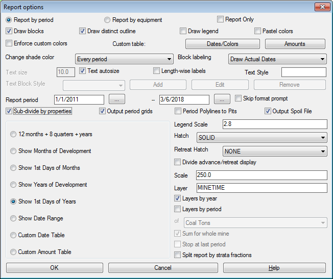 This
example will show the first days of months. This leads to the
final hatching shown below as bench 1(the bench 2 layers were
frozen for better appearance), as well as the quantity report which
can be formatted many different ways and exported to Excel or
Access:
This
example will show the first days of months. This leads to the
final hatching shown below as bench 1(the bench 2 layers were
frozen for better appearance), as well as the quantity report which
can be formatted many different ways and exported to Excel or
Access: