|
|
This command creates pits of the desired advance width by
intersecting a closed pit polyline and a direction line indicating
the direction the pits will be developed. In the first 2 examples
below the outcrop has been created as the outer limit of the pit.
The first example shows the impact of laying out a straight
direction polyline. The direction polyline must enter the pit
boundary from outside and exit the boundary to be valid. The
program advances along the direction polyline the distance entered
for the Cut Advance and intersects for each pit 90 degrees from the
direction line. There are two options on where to start the
advance. The first is at the end of the direction line and the
second is where the direction line intersects the pit boundary.
Most of the time the second option is used. The main use for
starting the advance at the beginning of the direction line is if
all direction lines start at a known "station" , then all pit
blocks will be uniform, named by station and in line with each
other.
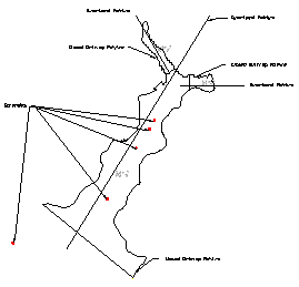
Example 1 uses a straight directional polyline and was done in 3 sections. Each pit is drawn 90 degrees from it at the desired Cut Advance.
|
|
|
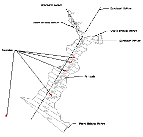
Example 2 uses a bent directional polyline to follow the contour of the outcrop. Here it uses a bent polyline to conform to the contour of the outcrop. The direction polyline cannot contain any arcs, however an arc can be initially drawn for the layout and converted to polyline segments using the command Remove Polyline Arcs on the Edit menu. Again, each pit is created by intersecting the direction line at a 90 degree angle. Going around corners will often look better with a smooth line, hugging the inside corner.
|
| Example 2 |
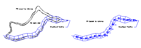
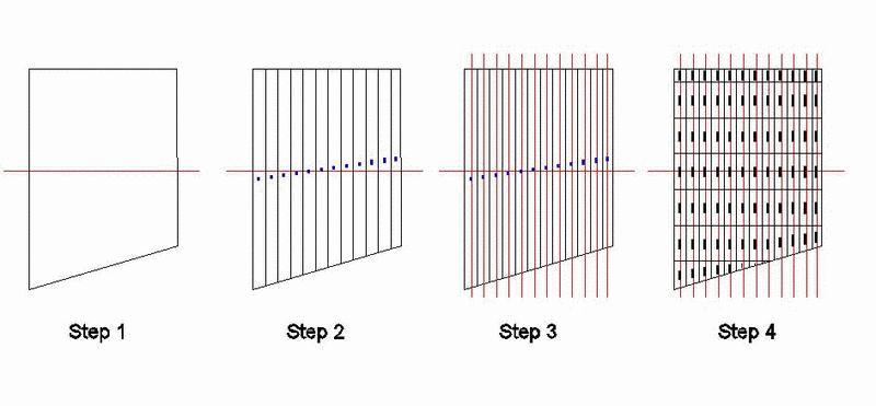
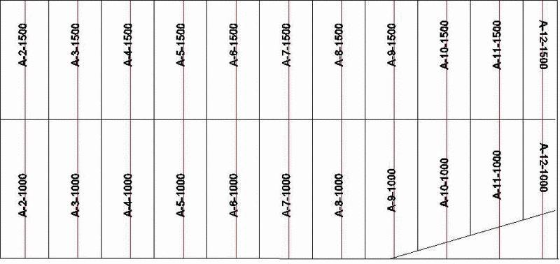
This third example will go through two iterations of Pit Layout by Advance to first create long strips of pits 175 wide, then break them into blocks that are 500 long, named with the appropriate stationing in the pit name. This is a unique application that is not apparent by just running the command, so a simple case study will follow. Step 1 is to create a mine boundary and draw a direction line through it. Step 2 is the first iteration of Pit Layout by Advance. This example used 175 for the pit width and created long strips of pits with a unique name, such as A-8 and A-9. Step 3 will prepare to break them up into blocks. First, create direction lines through each pit strip. The fastest way to do this is to draw the first direction line through the first strip. Then the ARRAY command will copy that multiple times, placing a direction line down the middle of each pit strip. Running the Pit Layout by Advance will first prompt to select the pit boundaries. Select all of the boundaries at once with a window, fence or by picking. Then it prompts to select the direction lines, select them all at once. In this type of example, the option to start advance at the beginning of the direction lines is chosen. This gives blocks that are named by station along the direction lines. Notice on the south end where the pit strips are not horizontal. Not using the option to calculate from the starting of the advance line will give pit blocks that are offset and not named by station along the direction centerlines. The pit blocks are created and can be labeled with Label Pit Polylines. Notice the pit names and the stationing of the pit blocks incrementing by 500, which is the length of each block.
Select all pit polylines.
Select objects: pick pit
polylines
Select all direction polylines.
Select objects: pick direction
polylines
Enter Cut Advance: 175
Enter Starting Sub-Pit Number: 1
Enter Sub-Pit Number Increment (1): 1
Calculate the advance from the start of the direction line
[Yes/<No>]? N
The highlighted pit does not have site and pit names assigned
Enter a site name: Site 2
Enter a pit name: A
Pulldown Menu Location: Boundary
Keyboard Command: cutpitadv
Prerequisite: A direction polyline and a closed pit area
polyline.