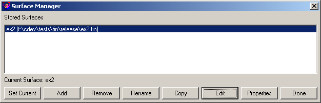
The Surface Manager toolkit allows the user to modify pre-defined triangulated surfaces, making real-time modifications and updates to contours and associated TIN (Triangulated Irregular Network) definitions. Functionality includes swapping TIN lines, adding breaklines to the surface, adding or removing points, adjusting point elevations, removing TIN lines, drawing or removing contour lines and labels, re-contouring at a different interval or with different label settings, etc. Contour lines are automatically updated to reflect any changes made to the TIN. A surface must be named and saved by of one of the surface modeling routines (in the Triangulate tab) as a prerequisite to using the Surface Manager tools.
 The Surface Manager dialog box
contains the following options:
The Surface Manager dialog box
contains the following options:Set Current designates a
surface as current for editing with various surface tool functions,
such as modifying TIN lines, setting a new contour interval,
labeling contours, etc.
Add allows you to add a
surface by selecting a surface model file (.TIN or .FLT).
Remove
allows you to remove a surface from the list of stored
surfaces.
Rename
allows you to rename a surface.
Copy
creates a copy of the TIN file and adds the copy as a new
entry.
Edit allows you to perform various TIN-related modifications to the current surface. Using the Edit function will activate the command line, where the user will be prompted with the following options:
Add Point
(AP) adds a triangulation point to the network by picking a
point from the screen. The pick must be inside an existing
triangle. The elevation for the selected point is interpolated from
the surrounding TIN network. This is a good method for adding
additional triangulation to the surface in a sparse area. Also, a
new elevation can be specified for the picked point. This function
does not create Carlson points, and the point will not be saved to
the .CRD file.
Remove Point (RP)
removes an existing triangulation intersection from the TIN
network. The affected triangulation re-adjusts to compensate for
the missing intersection. Contours update accordingly.
Move Point (MP) is
a combination of removing a point and adding it at a new
location.
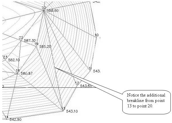
Add Breakline (AB)
adds a breakline to the surface by picking beginning and ending
points on the screen. The endpoint snap automatically turns on.
Only one breakline can be created at a time. The TIN network will
reconfigure to follow the new breakline and update the contours.
This does not create 3d polylines in the drawing.
Add Entities (AE) adds a number of points and breaklines
into the selection set by selection of existing entities into the
current surface.
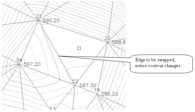
Swap Edge edges
(SW) swaps common TIN edges to create two different
triangles from the original triangle configuration. Contours
automatically update to reflect changes made to the TIN. Some
common edges may not be swapped because of the orientation of the
two triangles.
Set Elevation (SP)
Sets a new elevation for a specified TIN intersection. The affected
TIN is adjusted and the contours are updated.
Remove Tri (RT)
removes a TIN line from the surface by picking a TIN line or
selecting an interior point. Contours are removed from the affected
area.
Hide Tris (ST)
turns the TIN network on and off.
Point addition/removal and elevation-related
changes made to the TIN are only reflected in the surface file and
the contours resulting from that surface file. Point changes are
not saved to the .CRD file and 3D linework is not updated in the
drawing. Use traditional methods to update these entities if
desired.
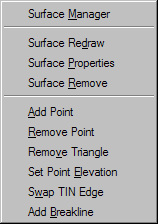
The command line will prompt as follows:
Add Pnt(AP),Remove Pnt(RP),Move
Pnt(MP),Set elev(SP),Add Breakline(AB),
Add Entities(AE), SWap edge(SW),Remove Tri(RT),Show/Hide Tris(ST),
Press Enter when done.
Adding points, Pick point or enter keyword: Type in the two
letters of the function to be performed and press enter.
Add
Points
Add Pnt(AP),Remove Pnt(RP),Move Pnt(MP),Set
elev(SP),Add Breakline(AB),
Add Entities(AE), SWap edge(SW),Remove Tri(RT),Show/Hide Tris(ST),
Press Enter when done.
Adding points, Pick point or enter keyword: Press Enter to
accept the default mode of Adding Points. Pick a point inside the
TIN model at the desires location. The default elevation will be
interpolated from the TIN model.
Enter the elevation of new point
[559.112171]: 560
The surface will be recalculated using the input data.

Remove
Points
Add
Pnt(AP),Remove Pnt(RP),Move Pnt(MP),Set elev(SP),Add
Breakline(AB),
Add Entities(AE), SWap edge(SW),Remove Tri(RT),Show/Hide Tris(ST),
Press Enter when done.
Adding points, Pick point or enter keyword: RP Pick close to the area that you
want an elevation point removed.
Add
Breakline
Add
Pnt(AP),Remove Pnt(RP),Move Pnt(MP),Set elev(SP),Add
Breakline(AB),
Add Entities(AE), SWap edge(SW),Remove Tri(RT),Show/Hide Tris(ST),
Press Enter when done.
Adding points, Pick point or enter
keyword: AB
Pick near the 1st point of
breakline: Pick a
point
Pick near the 2nd point of
breakline: Pick a
point When adding a breakline, OSNAP Endpoint will default
on.
Swap
Triangle Edge
Add Pnt(AP),Remove Pnt(RP),Move
Pnt(MP),Set elev(SP),Add Breakline(AB),
Add Entities(AE), SWap edge(SW),Remove Tri(RT),Show/Hide Tris(ST),
Press Enter when done.
Adding points, Pick point or enter
keyword: SW
Please select an internal edge to
swap: Select desired edge.

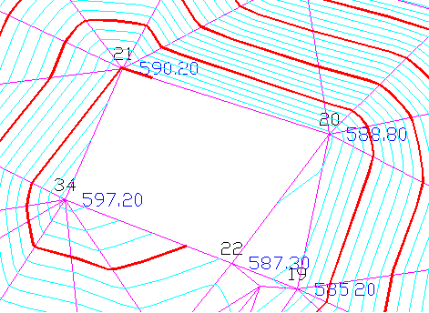
Set Point
Elevation
Add
Pnt(AP),Remove Pnt(RP),Move Pnt(MP),Set elev(SP),Add
Breakline(AB),
Add Entities(AE), SWap edge(SW),Remove Tri(RT),Show/Hide Tris(ST),
Press Enter when done.
Adding points, Pick point or enter
keyword: SP
Pick near the point to have
elevation set: Pick near point 34.
Enter new elevation of the point
[597.200000]: 600
Remove TRI
Line
Add Pnt(AP),Remove Pnt(RP),Move Pnt(MP),Set elev(SP),Add
Breakline(AB),
Add Entities(AE), SWap edge(SW),Remove Tri(RT),Show/Hide Tris(ST),
Press Enter when done.
Adding points, Pick point or enter keyword: RT

To conclude the Surface Edit mode, press Enter at the end of the internal command sequence. This will return to the Surface Manager dialog. If user presses Escape key instead, the following dialog is displayed:
 this prevents accidental data loss in
case of unintentional use of Esc key.
this prevents accidental data loss in
case of unintentional use of Esc key.
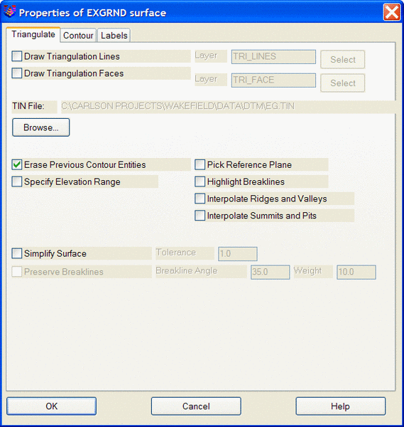
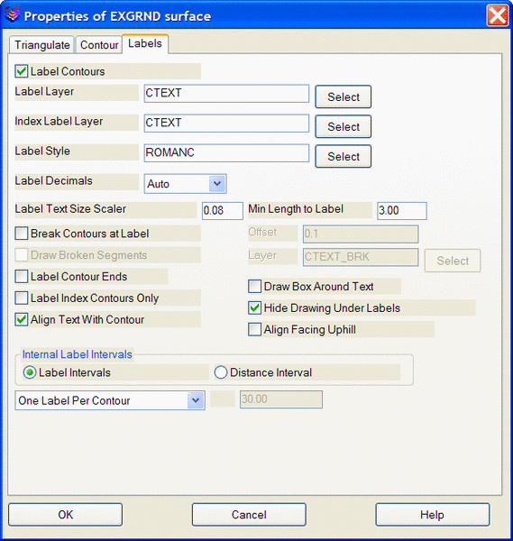
Properties
allows the user to alter the drawing display properties for TIN
lines, contours and labels for the selected surface. Applicable
dialogs from Triangulate and Contour are used to provide a full set
of options. When accessed, settings for the current surface display
configuration are set. To make a modification, simply specify the
desired change and press ok. For instance, if Draw Triangulation
Lines was checked on, unchecking the box and pressing ok will
redraw the surface without the TIN lines. If the contours were
drawn at 1 foot intervals, setting the interval value to
2 and pressing
OK will redraw the
contours at 2 foot intervals. Refer to the Triangulate and Contour section of the
manual for a more detailed explanation of the options below.

 Done exits the Surface Manager and
saves any modifications performed to the surface/s updating the
.flt or .tin file.
Done exits the Surface Manager and
saves any modifications performed to the surface/s updating the
.flt or .tin file.Pulldown Menu Location: Surface >> Triangulation
Surface Manager
Keyboard Command: surface_mgr
Prerequisite: A triangulated (non-grid) surface