
This command allows you to modify TIN surfaces in a variety of different ways, then allows for 3d viewing and shading of the modified surface and finally for saving the file with a choice of output formats. The focus of the routine is to elevate or lower the TIN or selected areas within the TIN, merge TINs with other surfaces, or use data from other TIN files to apply to the current TIN. Operations can be performed on the entire TIN or just on user selected Inclusion and/or Exclusion areas. The routine will automatically rework the TIN network for conformation to a selected boundary, say a building outline. In the case of said building, a value of 10 could be subtracted from the building outline. This will drop all of the triangulation within the outline by 10', thus creating a model of the excavated area for the building. The modified TIN can then be saved to a new file, which could be used to compute an excavation volume with Volumes by Triangulation. This routine does not allow for manual reconfiguration of the TIN network. This is performed under Surface Tools, also in the Contour pulldown menu. This routine also includes conversions to and from TIN files, DXF files and 3D Face entities.
Begin with the dialog shown here. First select a TIN model. You may choose between an .flt or .tin file, a DXF file (that includes 3DFACE entities), or 3DFACE entities in the current drawing. Specify the subject area by choosing inclusion or exclusion perimeters, then press the next button.
Load TIN File: Allows you to specify a triangulation (.flt or .tin) file to load.
Load DXF File: Allows you to specify a DXF file to load. Only loads 3DFACE entities from the selected DXF file.
Select 3D Faces: Allows you to select 3DFACE entities from the current drawing. This also includes rectangular 3d faces from a plotted grid.
Pick Bounding Polylines: Allows you to select any inclusion/exclusion perimeter(s). When this button is selected, the user is taken back to the drawing and prompted to select the perimeters. Press Enter when the selections are finished to return back to the dialog.
Fast TIN Intersect: When checked, this command will
perform a simple and fast check for overlapping triangles, so is
the preferred choice in most cases. However, if problems with
the TIN are suspected, this option should be unchecked, so that a
complete and thorough check and repair of the TIN is
performed.
Fill-in-holes: When checked, any missing triangulation or
gap in the surface will be automatically filled in with additional
triangles. This option has to be set before loading the TIN file to
take effect.
Region Mode: This option
deals with nested or overlapping boundaries. When checked,
AutoCAD hatch pattern logic is applied, in which all nested
boundaries are used in an alternating fashion, so that an Inclusion
Boundary within an Exclusion Boundary is still recognized. If
this option is not checked, everything within an Exclusion Boundary
is ignored.
Next: Press this button to proceed to the next dialog after all selections have been made .
The next dialog allows you to perform mathematical operation(s) on the loaded TIN. Each operation is described below. Keep in mind that generally these operations are to be performed on an area inside your inclusion perimeter (but excluding anything inside your exclusion perimeters). If you do not specify any perimeters, the desired operation/s will be performed on the entire TIN.
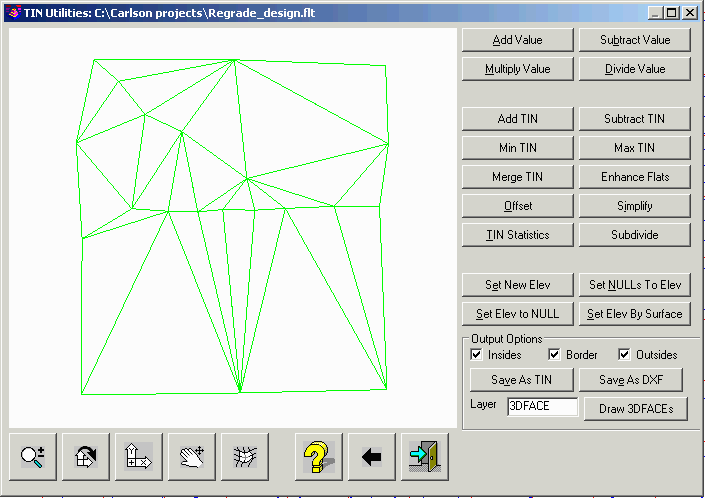
Add TIN: Raises the subject area of the current TIN by
the elevation value from a second user selected TIN file. This
function is most applicable to applying a strata thickness
TIN.
Subtract TIN: Lowers the subject area of the current TIN by the elevation value from a second user selected TIN file.
Min TIN: This does a comparison between the current TIN and a second user selected TIN file, and applies the lower value of the two TINs to the subject area.
Max TIN: This does a comparison between the current TIN and a second user selected TIN file, and applies the higher value of the two TINs to the subject area.
Merge TIN: Merges the current subject TIN into a second user-specified TIN file. There are three methods: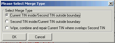

Set New Elev: Sets all TIN faces in the subject area to the elevation specified.
Set NULLs to Elev: Sets all NULL values in the subject area to the elevation specified.
Set Elev to NULL: Sets all of the elevation values in the subject area to NULL.
Set Elev by Surface: Sets all TIN faces within the subject area to the elevations from a second surface file within the same area. You will be prompted to select a second TIN file or grid file. Only areas common to both surfaces will be applied to the subject TIN.
Output Options: The following three options determine
what part or parts of the TIN modifications that will be saved to
the new TIN file. If the entire TIN is to be saved, all three
options should be toggled on.
Save As TIN: Saves the current TIN as an .flt or .tin file.
Save As DXF: Saves the current TIN as a .dxf file. This format can be used by many other CAD programs.
Draw As 3DFaces: Draws the current TIN as 3D Faces in the
current viewport. The Layer window is used to specify the layer
that the faces will be created in.
 Converts the left
mouse button to a zoom function. Hold the button down and move the
mouse up or down to zoom in and out.
Converts the left
mouse button to a zoom function. Hold the button down and move the
mouse up or down to zoom in and out.
 Converts the left
mouse button to a rotate function. Hold the button down to rotate
the view in any X, Y or Z direction. When the XY appears in the
window, the rotation will occur relative to the XY axis. When the
mouse is moved toward the outer perimeter of the window, the XY
will change to a Z. Holding the button down while the Z is visible
will rotate the drawing on the Z axis.
Converts the left
mouse button to a rotate function. Hold the button down to rotate
the view in any X, Y or Z direction. When the XY appears in the
window, the rotation will occur relative to the XY axis. When the
mouse is moved toward the outer perimeter of the window, the XY
will change to a Z. Holding the button down while the Z is visible
will rotate the drawing on the Z axis. Converts the left
mouse button to a pan function. Hold down on the button while
moving the mouse to pan. Holding down the mouse wheel will also
serve as a pan function in any of the above modes.
Converts the left
mouse button to a pan function. Hold down on the button while
moving the mouse to pan. Holding down the mouse wheel will also
serve as a pan function in any of the above modes. Toggles shading
on and off.
Toggles shading
on and off. Restores the
graphics to plan view.
Restores the
graphics to plan view. Reverses the
effects of all operations performed on the TIN and reverts it back
to its original status.
Reverses the
effects of all operations performed on the TIN and reverts it back
to its original status. This icon exits
the routine. If the TIN has been modified, you will be prompted to
save.
This icon exits
the routine. If the TIN has been modified, you will be prompted to
save.Pulldown Menu Location: Surface
Keyboard Command: TINUTIL
Prerequisite: 3D Faces, a TIN file or a DXF file.