This command allows you to create cross sections from a surface model. The stations for the sections, and the left and right offset distances, are defined in the MXS file. This file must be created before running this routine by using the Input-Edit Section Alignment command. The surface model is defined by lines or polylines with elevation. The polylines with elevation could be a contour drawing file from a photogrammetry firm, or it can be created from survey points with the Triangulate & Contour command. When using Triangulate & Contour it is useful to use the Draw Triangulation Lines option because the 3D triangulation lines represent all the breaklines in the surface which increases the accuracy of the cross section verses just using the contours. Breaklines or 3D polylines can also be used to represent ridges and valleys. The program samples the selected lines, polylines and 3DFace entities and calculates the intersections of these segments with any of the cross sections. The station, offset and elevation of these intersections make up the data in the section file. This section (.SCT) file can be reviewed or edited with the Input-Edit Section File command. Also, the section file can be plotted with the Draw Section File command or used in the by the Process Road Design command to calculate volumes.
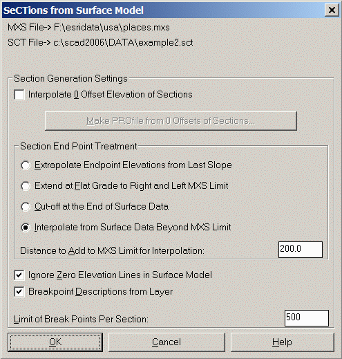
Interpolate 0 Offset Elevation of Sections: When checked,
this option will add a data point at offset zero for every station
with an elevation that is interpolated from existing offsets.
Make Profile from 0 Offsets of Sections: Allows you to specify
a .PRO file name to create from the 0 offsets of the sections.
Section End Point Treatment: The section end points are the
left and right furthest offsets such as left and right 100 feet.
When calculating sections based on the intersections with surface
entities, there usually isn't an intersection exactly at the end
points. For example, there could be contours at offsets right 87.31
and 105.43 but no intersection exactly at 100. There are four
methods for determining the elevation for these end points.
Extrapolate Endpoint Elevation from Last Slope: This option
calculates the slope from the last two offset-elevation points and
calculates the elevation at the endpoint from this slope. For
example, given offsets at 80 with elevation 100, and 90 with
elevation 101, the elevation at offset 100 would be 102.
Extend at Flat Grade to Right and Left MXS Limit: This option
uses the last offset elevation as the end point elevation. For
example, if the last offset were 85 with elevation 102, the program
would add an offset at 100 with elevation 102.
Cut-off at the End of Surface Data: This option does not add
offsets at the end points. The sections will end at the last offset
found in the surface model.
Interpolate from Surface Data Beyond MXS Limit: This option
looks beyond the offset limit for more intersections with surface
entities. The endpoint elevation is then interpolated between the
offsets above and below the endpoint. For example, given offsets at
90 with elevation 101, and at 110 with elevation 103, the endpoint
offset at 100 would have elevation 102. If this option is selected,
the Distance to Add to MXS Limit for Interpolation field becomes
available.
Distance to Add to MXS Limit for Interpolation: Enter
distance.
Ignore Zero Elevation Lines in Surface Model: When checked, all
zero elevations will be ignored.
Breakpoint Descriptions from Layer: When checked, this option
will store the layer name of the surface entity as the description
for the offset-elevation point in the section file.
Limit of Break Points Per Section: Specify the maximum number
of break points per section. Default value can be set using the
Section Defaults command.
MXS File to Process Select the section alignment .MXS
file
Section File to Write Specify the .SCT file
New or Append Choose
whether to create a new .SCT section file, or add to an existing
.SCT section file
Sections from
Surface Model dialog Make
selections
Select Lines, PLines, and/or 3DFaces that define the
surface.
Select objects: Pick the surface entities
Pulldown Menu Location: Sections
Keyboard Command: sctsm
Prerequisite: Constructed surface model (.MXS file) to be
sampled