This command creates section files in one step. The horizontal
alignment for the sections can be defined by using picked points, a
centerline file or a polyline. A section alignment (.MXS) file is
not required for this routine. 3D screen entities or surface files
(.GRD, .FLT, or .TIN) are used to define the vertical
alignment.
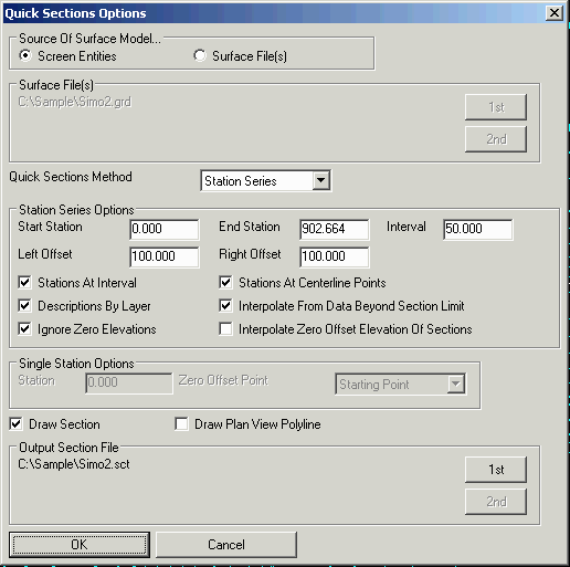
There are two options under Quick Section Methods. The Station
Series method creates sections perpendicular from the horizontal
alignment at a station interval. In this case, the horizontal
alignment represents the centerline. The Single Station method
creates one section along the horizontal alignment appends this
section to the output section file. In this case, the horizontal
alignment represents the alignment of the section.
For the Station Series method, there are settings for the Start
Station of the horizontal alignment, the End Station to stop
creating sections, the Interval for the stations, and the Left and
Right Offsets to define the section width. There are also options
to control the section stations to create. The Stations At Interval
option will create sections at the specified station interval. The
Stations At Centerline Points option will create sections at the
special stations of the centerline for the centerline transitions
such as PC, PT points
For the Single Station method, the Station value is assigned to
this section. The Zero Offset Point chooses between using the
starting point of the horizontal alignment as the zero offset or
selecting a point along the alignment as the zero offset.
With the Source Of Surface Model set to Surface Files, the
program prompts for up to two surface files so that up to two
section files can be generated at a time. When the Surface Model is
set to Screen Entities, only one section file is created from the
screen entities. With Screen Entities, there are a few more
options. The Descriptions By Layer option will use the layers of
the screen entities as the descriptions for the section points. The
Interpolate From Data Beyond Section Limit will check for
intersections with the section line and the screen entities beyond
the left/right offsets to interpolate the elevations at the
left/right offset extents. The Ignore Zero Elevations will filter
out screen entities that are at zero elevation. The Interpolate
Zero Offset Elevation Of Sections will create a section point at
offset zero by interpolating between the nearest section
points.
Pick starting point (CL-Centerline,P-Polyline): select
a point
Pick second point: select second point
Pick next point (Enter to end): press
Enter
Quick Section Options dialog
Choose Source of Surface Model, Screen Entities or Surface File,
and make other selections. Click OK.
Keyboard Command: quicksct
Prerequisite: 3D Screen entities or surface files