Point option dialog
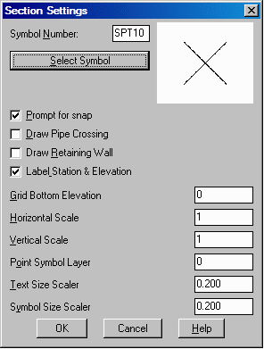
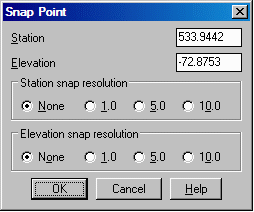
This command is step two in the Points on Section procedure. Before running this routine, the section or template sheet must be drawn on screen and there must be an existing coordinate (.CRD) file to read, with station and offset data in the description fields, as described under Points on Section. Station location points may also be picked on screen with the Points option. This command draws points on the section template from the coordinate (.CRD) file or via the Points method. If the Point option is selected, a Section Settings dialog appears, followed by a Snap Point dialog. The point elevation and the offset data in the description field are used to locate the point on the section.
Place points from .CRD file or pick points
[File/<Points>]? F
Enter the horizontal scale <1.0>: press
Enter
Enter the vertical scale <1.0>: press
Enter
Layer for points <PNTS>: press Enter
Select Coordinate File to Read Dialog pick a file You
select the crd file to process.
Range of Point Numbers to use (A for All) <A>:
press Enter for all points to process
Wildcard match of point description <*>: press
Enter for all points with or without descriptions
Plot Full or Abbreviated text (Full/<Abbrev>)?
F Here we used F for full description.
Range of stations: 117060.000 to 117090.000
Enter station to process: 117060
Enter search zone <1.0>: Search zone applies to survey
data collected in an approximate range plus or minus a small
distance on a known station.
Pick Center of Grid [int on]:
Pick a known elevation on the
centerline and on the next prompt enter that elevation.
Enter base elevation of grid: 278
Enter station to process: Enter next station or press
Enter to end
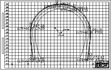
The points plot on the template or cross-section.
|
|
|
Point option dialog
|
|
|
|
Points plotted on template or
cross-section
|
Pulldown Menu Location:
Sections > Points On Section
Keyboard Command: ptsct
Prerequisite: Drawn section sheet and .CRD file with station
and offset description field data