This command calculates the offset and elevation at points along a polyline on a section grid. The results can be drawn on the grid or just displayed on the text screen. The offset and elevation are either calculated for each vertex of the polyline or at user specified points. This command can also be used as a section inspector. As you move the cursor across the section, the offset, elevation and slope are reported in real-time in a pop-up window.
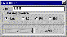
The Prompt For Snap toggle controls whether the command will
present the snap dialog as you pick points to figure the offset and
elevation at. The Grid Starting Elevation edit box allows you to
input the beginning elevation of the local grid that you are
designing in. Use the Scale edit boxes to set the proper horizontal
and vertical scales for your design environment. The Label each
vertex of grade polyline option will draw the offset-elevation
label above each point in the selected polyline. There are also
settings to control the prefix, suffix and decimal precision for
all the labels.
Section Offset-Elevation Settings dialog Choose the
scales and base elevation that match your section grid.
Pick center grid point [int on]: Pick the grid point at the
zero offset and base elevation. The intersection osnap mode is
on.
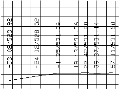
Pick grade polyline: select polyline
Pick vertical alignment for
text: pick point above the polyline
|
|
Offset & elevation at each
polyline vertex
|
Pulldown Menu Location: Sections
Keyboard Command: offelev
Prerequisite: Must plot the polyline that represents the
grade