Road Rehabilitation Profile
This command creates a profile that sets a road design at an
elevation to meet the specified overlay thickness along with
leveling or milling thickness. The rehabilitation profile created
by this command can then be used in Process Road Design to create
the rehabilitation design including the rehabilitation surface,
sections, quantities and linework.
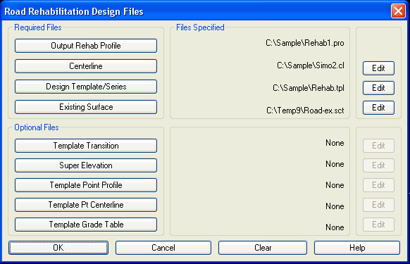 The first dialog specifies the road design files. All
these settings are the same as in Process Road Design except for
the Output Rehab Profile. This profile is the output result for
this command. The difference with Process Road Design is that the
profile is an output instead of an input. Please see the Process
Road Design section of the manual for a description of the other
input files.
The first dialog specifies the road design files. All
these settings are the same as in Process Road Design except for
the Output Rehab Profile. This profile is the output result for
this command. The difference with Process Road Design is that the
profile is an output instead of an input. Please see the Process
Road Design section of the manual for a description of the other
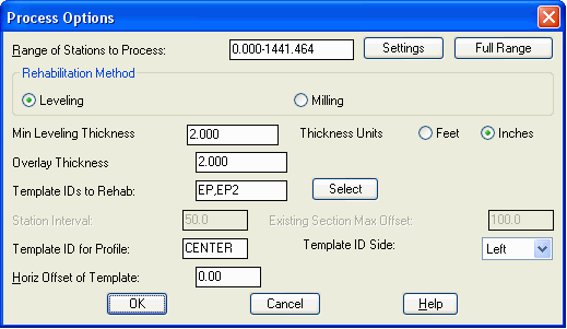
input files.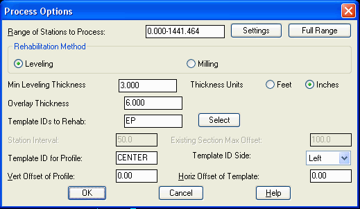 The second dialog has processing options. Again, many
of these parameters are the same as Process Road Design. The
settings specific to this command are the following:
The second dialog has processing options. Again, many
of these parameters are the same as Process Road Design. The
settings specific to this command are the following:
Rehabilitation Method: This chooses between adding a
leveling layer to the existing road or stripping the existing road
by milling or grinding.
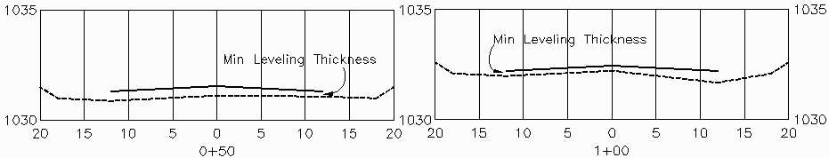
Minimum Leveling Thickness:
This is the minimum fill thickness between the existing road and
the bottom of the overlay subgrade of the new road.
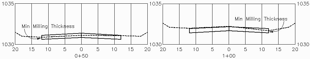
Minimum Milling Thickness:
This is the minimum cut thickness between the existing road and the
bottom of the overlay subgrade of the new road.
Overlay Thickness: This is
the depth of the overlay subgrade of the new road. This value
should match the subgrade thickness defined in the template.
Template IDs to Rehab:
These are the grade IDs from the template definition to process for
the overlay. The Select button can be used to graphically pick the
template IDs. Multiple IDs can be specified by entering the IDs
separated by commas. For example, if a road has two lanes with two
grades for overlay and the template IDs are LANE1 and EP, then
enter "LANE1,EP" in the dialog.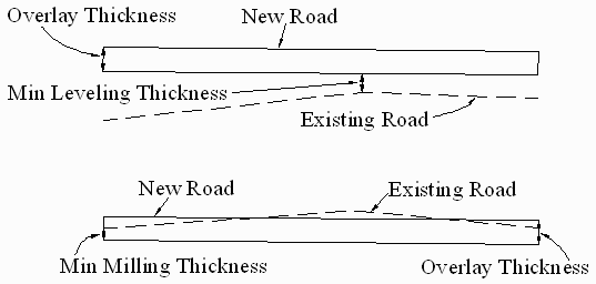
Example 1: Milling
In this case, the existing road will be trimmed by the specified
milling thickness.
Step 1: Define
Centerline
Use a routine from the Centerline menu to create the .CL file. For
example, for entering design plans, use Input-Edit Centerline File.
For using the geometry of a polyline, use Polyline To Centerline
File.
Step 2: Define Template
Run Design Template to create a .TPL file. In this case, the
template will be a two lane road with 12' lanes and -2% cross
slopes. That's the minimum that needs to be defined for the
rehabilitation design. The cut/fill slopes are not
required. Step 3: Existing
Surface
Step 3: Existing
Surface
The existing surface can be either a triangulation model or cross
sections of the existing road. To create a triangulation surface,
you need 3D data for the existing road (points and breaklines) and
then run Triangulate & Contour to create a .TIN file. To create
cross sections, use the routines in the Sections menu for
Input-Edit Section Alignment to set the section intervals and then
run one of the Create Section routines to make a .SCT file.
Step 4: Road Rehabilitation
Profile
Run this command and specify the 3 files created in steps 1-3. Also
set the output profile to create the .PRO file. On the second
dialog, choose the Milling method. Set the Milling Thickness to 3
inches. Set the Overlay Thickness to zero since the template
doesn't have a subgrade. Set the Template ID to EP to match the
grade from the template.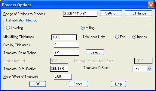 Step 5:
Process Road Design
Step 5:
Process Road Design
Run this command and specify the 4 files created in steps 1-4. Also
set the output Design Section file to create a .SCT file for the
rehabilitation design.
Output:
The report
includes the total cut and cuts per station which is the quantity
of the milling.
Process Road Design
Template File> C:\sample\rehab.tpl

Profile File> C:\sample\rehab1.pro

Existing Surface File> C:\sample\road-ex.sct

Centerline File> C:\sample\simo2.cl

Design Section Output File> C:\sample\rehab1.sct
Processing 0+00.000 to 14+41.464

Total Cut : 9203.469 C.F., 340.869 C.Y.

Total Fill: 0.000 C.F., 0.000 C.Y.
Use Input-Edit Section File or Draw Section File to view the design
and existing sections.
 Example 2: Milling with Overlay
This example adds an overlay thickness to the design from example
1. The steps are the same except for the following:
Repeat Step 2: Design
Template
Add a subgrade below the EP grade with a depth of 6
inches. Repeat Step 4: Road Rehabilitation
Profile
Repeat Step 4: Road Rehabilitation
Profile
Use the same settings as example 1 except set the
Overlay Thickness to 6 inches.
Repeat Step 5: Process Road
Design
Run this command again with the updated Template
and Profile.
Output:
The report includes the updated milling cut
quantities along with the overlay subgrade volumes. Since the
Milling Thickness stayed at 3 inches, the cut quantities stayed the
same as example 1. The Overlay Thickness being thicker at 6 inches
leads to more subgrade quantities and raises the new road above the
existing in areas.
Process Road Design
Template File> C:\sample\rehab.tpl

Profile File> C:\sample\rehab1.pro

Existing Surface File> C:\sample\road-ex.sct

Centerline File> C:\sample\simo2.cl

Design Section Output File> C:\sample\rehab1.sct
Processing 0+00.000 to 14+41.464

Total Cut : 9203.673 C.F., 340.877 C.Y.

Total Fill: 0.172 C.F., 0.006 C.Y.
Total Subgrade1 - Asphalt: 17295.031 C.F., 640.557 C.Y., 34592.253 S.F., 3843.584 S.Y.
 Example 3: Leveling
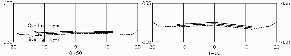
This example applies leveling to an existing road. The steps are
the same as example 1 except for the following:
Repeat Step 4: Road Rehabilitation
Profile
On the first dialog, use the same data files as
example 1. On the second dialog, choose the Leveling method. Set
the Leveling Thickness to 3 inches. Set the Overlay Thickness to
zero since the template doesn't have a subgrade. Set the Template
ID to EP to match the grade from the template.
 Repeat Step 5:
Process Road Design
Repeat Step 5:
Process Road Design
Run this command with the same
settings as example 1. The only difference is that the profile is
set for leveling instead of milling.
Output:
The report includes the total fill and fills per
station which is the quantity of the leveling.
Process Road Design
Template File> C:\sample\rehab.tpl

Profile File> C:\sample\rehab1.pro

Existing Surface File> C:\sample\road-ex.sct

Centerline File> C:\sample\simo2.cl

Design Section Output File> C:\sample\rehab1.sct
Processing 0+00.000 to 14+41.464

Total Cut : 0.000 C.F., 0.000 C.Y.

Total Fill: 8994.509 C.F., 333.130 C.Y.
 Example 4: Leveling with
Overlay
Example 4: Leveling with
Overlay
This example adds an overlay thickness with a minimum of 4 inches
to the design from example 3. Part of the overlay will be in the
subgrade of the template and the rest will be in the Min Leveling
Thickness setting. The steps are the same as example 3 except for
the following:
Repeat Step 2: Design
Template
Add a subgrade below the EP grade with a depth of 2
inches.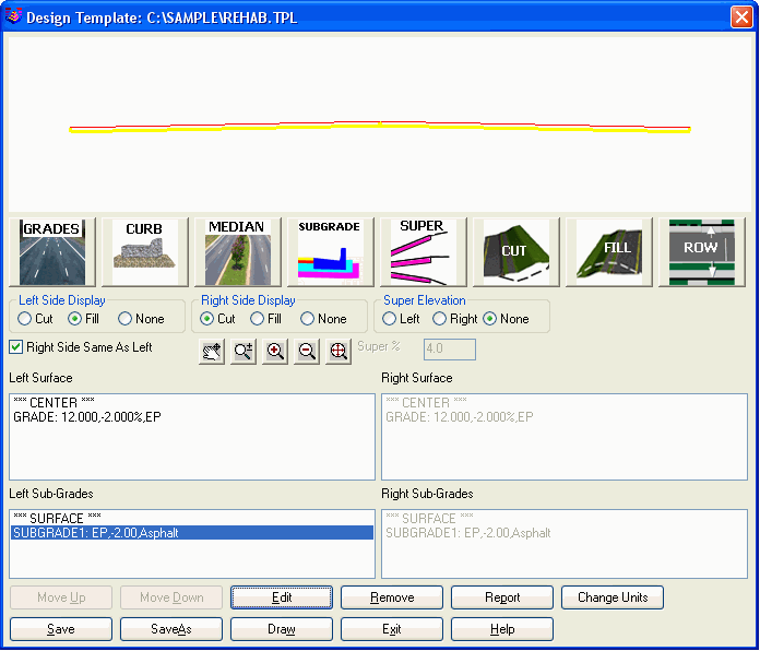 Repeat Step 4: Road Rehabilitation
Profile
Repeat Step 4: Road Rehabilitation
Profile
Use the same settings as example 3 except set the
Overlay Thickness to 2 inches and set the Min Leveling Thickness to
2 inches.
Repeat Step 5: Process Road
Design
Run this command again with the updated Template
and Profile.
Output:
The report includes the updated leveling fill
quantities along with the overlay subgrade volumes.
Process Road Design
Template File> C:\sample\rehab.tpl

Profile File> C:\sample\rehab1.pro

Existing Surface File> C:\sample\road-ex.sct

Centerline File> C:\sample\simo2.cl

Design Section Output File> C:\sample\rehab1.sct
Processing 0+00.000 to 14+41.464

Total Cut : 0.000 C.F., 0.000 C.Y.

Total Fill: 3228.086 C.F., 119.559 C.Y.

Total Subgrade1 - Asphalt: 5765.356 C.F., 213.532 C.Y., 34592.253 S.F., 3843.584 S.Y.
 Example 5: Leveling with Overlay and Match
Slopes
Example 5: Leveling with Overlay and Match
Slopes
This example modifies example 4 to have the new road cross slopes
match the existing cross slopes instead of being at a fixed design
of -2%. The steps are the same as example 4 expect for the
following:
Step 2: Define Template
There are several methods to modify the template for transitions.
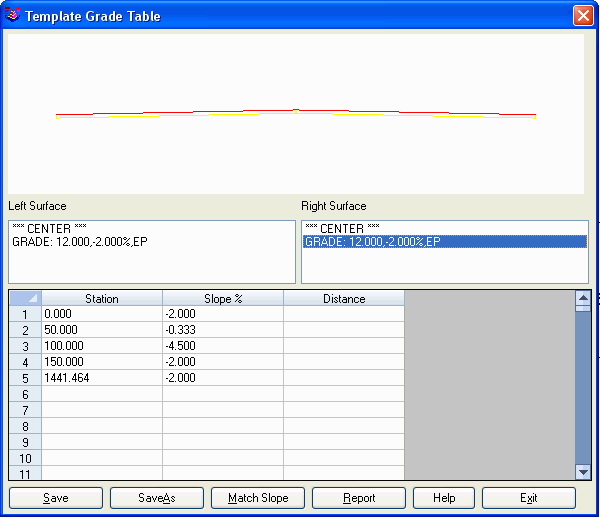
For this example, the Template Grade Table command is used. This
command defines slope and distance transitions for template grades.
In this example, we will only use the slope transitions to make the
design slopes match the existing road.
Run the Template Grade Table command and create a new .TGT file.
Select the rehab template that was used in example 4 as the
template to process. In the dialog, highlight the EP grade from the
list for the Left Surface. Then pick the Match Slope button. Select
the section file for the existing road. Next there is a dialog to
set the range of stations to process and the reference offset
points which are used to sample the existing surface to get the
slope between these offsets. In this example, the full station
range is used and the offsets are 0 for the center and -12 for the
left EP.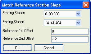 Next, highlight the EP grade
from the list for the Right Surface. Then pick Match Slope and
select the existing section file. For the offsets, use 0 and
12.
Next, highlight the EP grade
from the list for the Right Surface. Then pick Match Slope and
select the existing section file. For the offsets, use 0 and
12. Then back on the main dialog, pick
the Save button.
Then back on the main dialog, pick
the Save button.
Repeat Step 4: Road Rehabilitation
Profile
Use the same settings as example 4 except set the
Template Grade Table on the first dialog.
Repeat Step 5: Process Road
Design
Run this command again with the updated Template
and Profile.
Output:
The report includes the leveling fill quantities
along with the overlay subgrade volumes.
Process Road Design
Template File> C:\sample\rehab.tpl

Profile File> C:\sample\rehab1.pro

Existing Surface File> C:\sample\road-ex.sct

Centerline File> C:\sample\simo2.cl

Template Grade Table File> C:\sample\simo2.tgt

Design Section Output File> C:\sample\rehab1.sct
Processing 0+00.000 to 14+41.464

Total Cut : 0.000 C.F., 0.000 C.Y.

Total Fill: 5765.382 C.F., 213.533 C.Y.

Total Left Subgrade1 - Asphalt: 2882.684 C.F., 106.766 C.Y., 17296.127 S.F., 1921.792 S.Y.

Total Right Subgrade1 - Asphalt: 2882.681 C.F., 106.766 C.Y., 17296.127 S.F., 1921.792 S.Y.
 Example 6: Leveling with Overlay and SuperElevation
plus Lane Widening
Example 6: Leveling with Overlay and SuperElevation
plus Lane Widening
In this variation, the new road has both overlay and new design
changes of applying new superelevation and widening a lane. The
steps that are different than example 4 are described
here.
Step 2: Define Template
For this example, the template has additional design elements
besides the overlay grades. Run the Design Template command to add
the new elements. 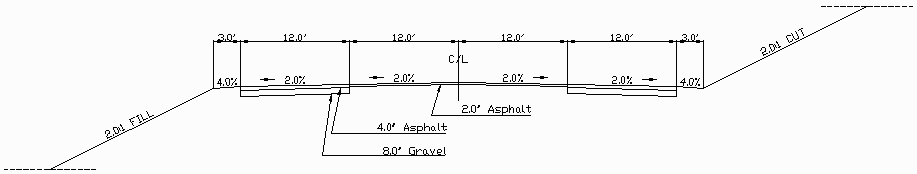 First, pick the
Grades button to add a new grade for the new lane using a slope of
-2%, distance of 12 and ID of EP2. Then add a new grade for a
shoulder with slope of -4%, distance of 3 and ID of SH. Next,
subgrades are needed for the new lane since this isn't over the
existing road. Add a subgrade of 4 inches of asphalt under the new
lane and another subgrade of 8 inches of gravel. Next pick the Cut
button and set the cut slope to 2:1 and pick the Fill button and
set the fill to 2:1. The cut/fill slopes are needed to tie the new
road design elements to the existing surface.
First, pick the
Grades button to add a new grade for the new lane using a slope of
-2%, distance of 12 and ID of EP2. Then add a new grade for a
shoulder with slope of -4%, distance of 3 and ID of SH. Next,
subgrades are needed for the new lane since this isn't over the
existing road. Add a subgrade of 4 inches of asphalt under the new
lane and another subgrade of 8 inches of gravel. Next pick the Cut
button and set the cut slope to 2:1 and pick the Fill button and
set the fill to 2:1. The cut/fill slopes are needed to tie the new
road design elements to the existing surface.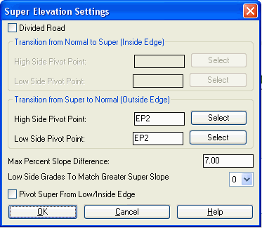 Finally, pick the Super button to set the
superelevation transition ID's as EP2 so that the shoulder stays
outside the super. Then pick the Save button.
Finally, pick the Super button to set the
superelevation transition ID's as EP2 so that the shoulder stays
outside the super. Then pick the Save button. Even though
the template has the new lane EP2 defined for both sides, let's
actually only apply this new lane for a range of stations on the
left side. Run the Template Grade Table command and make a new .TGT
file. Select the template file that was just created. Then pick EP2
on the Right Surface list. In the table, fill in the first row with
station 0 and a distance of 0. This will eliminate EP2 on the right
side. Then pick on EP2 from the Left Surface list. Fill out the
table as shown to make the new lane start at station 3+00, reach
full size at 3+36, start transitioning back at station 9+00 and
return to zero at station 9+36.
Even though
the template has the new lane EP2 defined for both sides, let's
actually only apply this new lane for a range of stations on the
left side. Run the Template Grade Table command and make a new .TGT
file. Select the template file that was just created. Then pick EP2
on the Right Surface list. In the table, fill in the first row with
station 0 and a distance of 0. This will eliminate EP2 on the right
side. Then pick on EP2 from the Left Surface list. Fill out the
table as shown to make the new lane start at station 3+00, reach
full size at 3+36, start transitioning back at station 9+00 and
return to zero at station 9+36.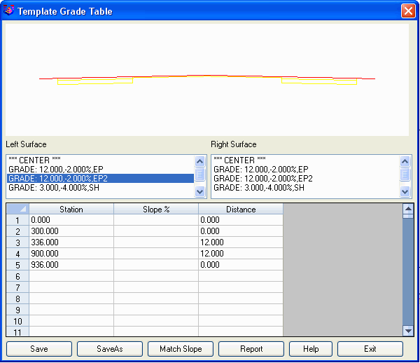 Another
template transition definition to create is the superelevation. Run
the Input-Edit Super Elevation command and create a new .SUP file.
Use the option to select a centerline and specify the speed table
to have the program set the transition stations. Or use the Add
function to manually enter the transition stations and full super
slope.
Another
template transition definition to create is the superelevation. Run
the Input-Edit Super Elevation command and create a new .SUP file.
Use the option to select a centerline and specify the speed table
to have the program set the transition stations. Or use the Add
function to manually enter the transition stations and full super
slope.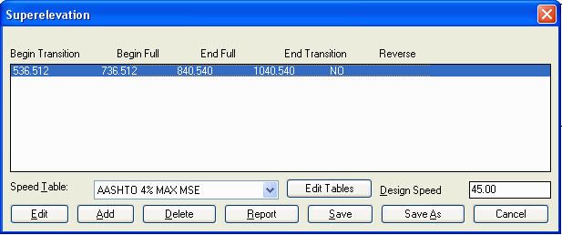 Repeat Step 4: Road
Rehabilitation Profile
Repeat Step 4: Road
Rehabilitation Profile
Use the same settings as example 4
except use the new template (TPL), template grade table (TGT) and
superelevation (SUP) created in step 2.
Repeat Step 5: Process Road
Design
Run this command again with the new template,
profile, template grade table and superelevation.
Output:
The report includes the leveling fill quantities
along with the overlay subgrade and the quantities for the new road
elements.
Process Road Design
Template File> C:\sample\rehab.tpl

Profile File> C:\sample\rehab1.pro

Existing Surface File> C:\sample\road-ex.sct

Centerline File> C:\sample\simo2.cl

Template Grade Table File> C:\sample\rehab.tgt

SuperElevation File> C:\sample\rehab.sup

Design Section Output File> C:\sample\rehab1.sct
Processing 0+00.000 to 14+41.464
Total Cut : 3549.129 C.F., 131.449 C.Y.
Total Fill: 22519.407 C.F., 834.052 C.Y.
Total Left Subgrade1 - Asphalt: 2882.699 C.F., 106.767 C.Y., 17296.127 S.F., 1921.792 S.Y.
Total Left Subgrade2 - Asphalt: 2399.867 C.F., 88.884 C.Y., 7200.000 S.F., 800.000 S.Y.
Total Left Subgrade3 - Gravel: 4799.622 C.F., 177.764 C.Y., 7200.000 S.F., 800.000 S.Y.
Total Right Subgrade1 - Asphalt: 2882.569 C.F., 106.762 C.Y., 17296.127 S.F., 1921.792 S.Y.
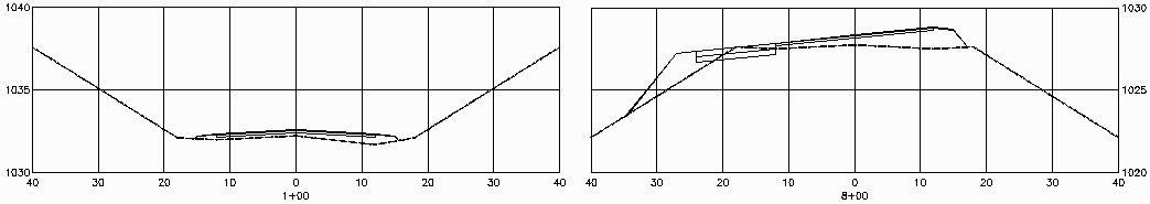
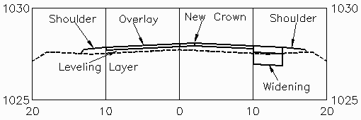
These sections show the road at a station before the new lane and superelevation and at a station with the new lane and superelevation.
 Example 7: Leveling with Overlay with Lane Widening
at New Crown position
Example 7: Leveling with Overlay with Lane Widening
at New Crown position
In this variation, the existing road has two 10' lanes that are
being expanded to 12' lanes. The left EP is staying fixed and the
extra 4' is added to the right side. So the crown is shifting 2' to
the right. The steps are the same as example 4 except for the
changes to the template definition.
Step 2: Define Template
Use the Define Template command to make the template overlay and
widening grades. For this example, there is one 10' grade on the
left side for the overlay plus a 3' shoulder. On the right side,
there are four grades. The first right side grade is 2' for the
portion of the overlay that is shifting the crown over. The second
grade is 8' for the remainder of the right side overlay. The third
grade is 4' for the widening. The fourth grade is a 3' shoulder.
The template has subgrades of 2" for the overlay grades and has two
subgrades of 4" of asphalt and 8" of gravel for the widening grade.
Since this template is asymmetrical, uncheck the toggle for Right
Side Same As Left.
Next pick the Cut button and set the cut slope to 2:1 and pick the
Fill button and set the fill to 2:1. The cut/fill slopes are needed
to tie the new road design elements to the existing
surface.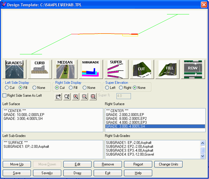 Repeat Step 4: Road
Rehabilitation Profile
Repeat Step 4: Road
Rehabilitation Profile
For the input files, use the
template created in step 2, the centerline and existing surface.
For the process options, choose the Leveling method and enter 2
inches for the Leveling and Overlay thicknesses. For the Template
IDs, specify both EP and EP2 since both of these are overlay
grades.
 Repeat Step
5: Process Road Design
Repeat Step
5: Process Road Design
Run this command with the new
template and profile.
Output:
The report includes the leveling fill quantities
along with the overlay subgrade and the quantities for the new road
elements.
Process Road Design
Template File> C:\sample\rehab.tpl

Profile File> C:\sample\rehab1.pro

Existing Surface File> C:\sample\road-ex.sct

Centerline File> C:\sample\simo2.cl

Design Section Output File> C:\sample\rehab1.sct
Processing 0+00.000 to 14+41.464

Total Cut : 3462.106 C.F., 128.226 C.Y.

Total Fill: 8523.772 C.F., 315.695 C.Y.

Total Left Subgrade1 - Asphalt: 2402.152 C.F., 88.969 C.Y., 14413.199 S.F., 1601.467 S.Y.

Total Right Subgrade1 - Asphalt: 479.988 C.F., 17.777 C.Y., 2881.487 S.F., 320.165 S.Y.

Total Right Subgrade2 - Asphalt: 1921.865 C.F., 71.180 C.Y., 11531.712 S.F., 1281.301 S.Y.

Total Right Subgrade3 - Asphalt: 1921.510 C.F., 71.167 C.Y., 5765.856 S.F., 640.651 S.Y.

Total Right Subgrade4 - Gravel: 3842.962 C.F., 142.332 C.Y., 5765.856 S.F., 640.651 S.Y.
Pulldown Menu Location: Roads
Keyboard Command: rdrehab
Prerequisites: Centerline, template and surface
files