The primary function of this command is to assemble all of the components for a road design and process them together. While all of the Input Files can be created prior to accessing the Process Road Design command, all can be edited from the Road Design Files dialog, and many files can actually be created from the Road Design Files dialog itself. The actual processing of the Road Design essentially applies the design template at the design profile elevation along the specified centerline and computing the outslopes and earthworks relative to the existing ground surface. The earthworks report can be shown in the standard report viewer or customized with the Report Formatter option. Secondary functions include creating a final grade section file for plotting with the Draw Section File command, creating final grade points in a coordinate file, creating a final surface/contour model, and drawing the road as 3D polylines. You can also output a mass haul diagram profile. The program also has options for applying a superelevation file, template transition file, template point profile, template point centerline, rock section file, an as-built existing section file and a topsoil removal file. Process Road Design can be used not just for final road design computations but for levees, channels and any template-based application.
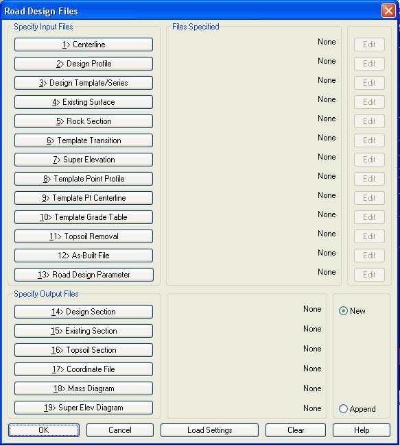
This command begins with the dialog shown below. The top section contains input Files. In a typical implementation of this command, you will have already defined a horizontal centerline for the design to follow, however, you could actually pick the Centerline button, pick the New tab, name the new centerline file (.CL), pick Open, and then back in the main Road Design Files dialog, pick the Edit button and layout the centerline design. The only component that you must have already created before running Process Road Design is #4, an Existing Surface file. As long as there is an Existing Ground Surface, the command will generate the Existing Ground Profile automatically, and the Proposed Finish Grade Profile can be created with the Edit button. Even a Design Template can be created right from here as well. Ultimately, the top 3 Input items (Centerline, Design Profile, and Design Template/Series) are required to Process a Road Design, leading to final sections and full contouring and 3D viewing. The Existing Surface is needed as well to process with earthwork calculations and tie slopes.
Input items 5 through 11 are strictly optional design files. It should be pointed out that items 8 and 9 (Template Point Profile and Template Point Centerline) enable template IDs to follow any defined centerline or profile and provide total flexibility of design. Lane widening, matching existing curb lines, special ditches, etc. can be easily accomplished with these two options. The template IDs simply "string along" or follow these pre-defined alignments, and the rules of the template apply to all other template ID points.
The Output Files section allows you to specify files to store
the processing results. The Section File creates a final grade
section file that can be drawn with Draw Section File. The
Topsoil Section File creates the modified existing ground section
file if Topsoil Removal is set in the input. This "post-topsoil
removal" section file can be used for earthworks calculations to
compare any stage of work, using Calculate Sections Volume
under the Section pulldown menu. The Coordinate File creates a
coordinate file containing every break point in the final grade.
The point descriptions include the station, offset and template ID.
Whether to include the subgrade points as well as the final surface
points is determined by the Include SubGrade Points in Output CRD
File option on the next dialog. To the right of the Output Files is
the option to create new output files or append to existing output
files. If you extend the road, or revise a portion of the project,
you can simply "Append" rather than overwrite. The first time
that you run this command for stations 0-1000, you would set Output
Files to New. Then you could run this command again, possibly with
new inputs, for stations 1000-2000 and set Output Files to
Append.
On the next dialog, there is a Save Settings button to store all
the settings from the first and second dialogs into a specified
Road Design File with an (.RDF) file extension. Recorded (.RDF)
files can be recalled later using the Load Settings option.
1>
Centerline
Specify the name of the Centerline file with this option. The
(.CL) file contains the horizontal alignment geometry for a
project. This parameter file must be specified if you want to have
earthworks centroid corrections computed, generate final
coordinates, Disturbed Area Polyline, and/or use Triangulate &
Contour. The centerline file can be created by the Design
Centerline or Polyline to Centerline commands in the
Design pulldown menu.
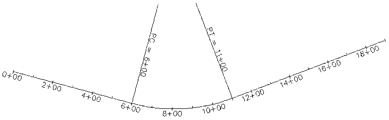 Example
Centerline
Example
Centerline
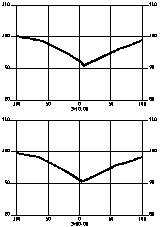
Specify the design profile (.PRO) file to derive the centerline
elevations when the template is applied. This file defines the
vertical alignment and is always required. The profile can be
created with any of the profile creation routines in the Profile
menu, but typically you would use Design Road Profile or
Input Edit Profile.
 Example Design
Profile
Example Design
Profile
3> Design Template/Series
Specify a template definition (.TPL) file or template series
(.TSF) file that defines the final grade offsets and elevations and
the cut/fill slopes. The template file is created by the Design
Template command and the template series file (a set of
templates ordered by range of stations) is created using
Input-Edit Template Series. A single template file or a
template series file is required to run Process Road
Design.
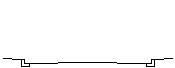 Example Design
Template
Example Design
Template4> Existing Surface
Specify the surface model which will be treated as the existing
ground for cut and fill volumes and to calculate the outslope
intersections when the template is applied at the profile
elevations. This Existing Surface can be defined by either a
section file or triangulation. The section file can be created with
commands such as Sections from Surface Entities,
Input/Edit Section File, Sections from Points or one
of the Digitize Sections commands on the Section menu. The
triangulation file can be created with the Triangulate & Contour command.
 Example Existing Sections
This option specifies an optional rock
section file that is used as an additional surface. When in cut, a
special cut slope is used up to the intersection of the rock
surface. After this intersection, the normal cut slopes apply. The
special rock cut slope is specified in Design Template under the
cut options. If the "pivot point" in cut is below the rock
line, then the special rock cut slope will be applied. Note that
rock sections can be derived from borings to rock, as modeled, or
can be created quickly by using the "translate" command within
Input-Edit Section File to translate the existing ground
sections by a vertical offset (e.g. -6) to an approximate top of
rock. 
6> Template Transition File
Specify a .TPT file with this option. The Template Transition
file allows modified template files to be applied at different
ranges of stations on a project. In this way, template IDs can be
made to widen (as for passing lanes) and contract. Use the
Template Transition command under the Design menu to create
a template transition file.
7> Super Elevation File
This option is used to specify a super elevation file (.sup file) that defines the super elevation transition stations on a project. The super elevation file can be created with the Input-Edit Super Elevation command.
8> Template Point Profile
This option lets you have separate profiles for template points that are independent of the centerline profile. This design file is created with the Assign Template Point Profile command.
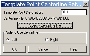
9> Template Point Centerline
This option lets you have separate centerlines for template points that are independent of the main centerline. This design file is created with the Assign Template Point Centerline command.
10> Template Grade Table
This input file is optional. The Template Grade Table is a method for template transitions that uses a lookup table of distance and slopes at transition stations for each template ID. This design file is created with the Template Grade Table command.
11> Topsoil Removal
This option applies topsoil removal and/or replacement to the existing ground section file. This design file is create with the Topsoil Removal/Replacement command.
12> As-Built File
The As-Built File is a cross section file used to match existing grade and retain as-built portions of a road improvement project. The final cross sections will conform to the as-built cross sections for those template IDs specified in the second dialog. Beyond the specified set of offsets in the as-built cross section file, the design road files will be applied.
13> Road Design Parameter
This input file is optional for running checks on the road design for parameters such as min sight distance and max grades. This .RDP file is created with the Define Road Design Parameters command.
14> Output Design Section File
Specify the name of the file to output the final grade sections calculated by applying the template file at profile elevations and calculating the outslope intersection with the existing ground cross sections. This file can then be plotted by using the Draw Section File command. After plotting the final sections overlaid on the existing sections, revisions can be made graphically with commands like PEDIT and Polyline by Slope Ratio. The data output to the file can also be edited and reviewed with the Input-Edit Section File command. If the final sections are edited graphically, the revised section data can be updated in the .SCT file with the Polyline to Section File command.
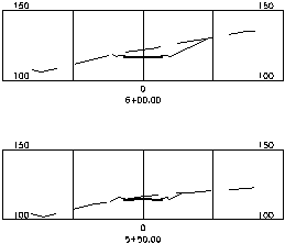
Output Section File drawn with Existing Section File by the Draw Section File command
15> Output Existing Section File
This option creates a section file of existing ground. This applies when the existing surface is a triangulation file. The station intervals for the existing section file will match the stations from the design section file.
16> Output Topsoil Section File
This option writes out a modified existing ground section adjusted by the topsoil removal. This option is only valid if a Topsoil Removal file is being used.
17> Output Coordinate File
This option creates a coordinate file containing every break point in the final grade for the range of processed stations. Using the second dialog, there are additional options to output subgrade and ditch/berm points. The point descriptions include the station, offset and template ID. The station interval is set by the stations in the Existing Section File.
18> Output Mass Diagram File
The mass haul diagram can be output as a profile file and shows
the cumulative cut and fill along the selected range of stations.
Cut and fill is balanced between points on the mass haul profile
that cross the Z-axis. Because of the typically large values of cut
and fill associated with road and earthwork projects, the vertical
scale for the profile may need to be set to 10 times the horizontal
scale, or more. The profile preview screen which appears when you
select profile for loading will show the elevation range and help
suggest an appropriate vertical scale.
19> Super Elevation Diagram File
This option writes out a super elevation transition file (.SUD)
that can be used with the Draw Super Elevation Diagram routine.
This file contains the template cross slopes and the transition
stations.
Running the Road Design Job
After setting up the files and options in the first dialog click
the OK button. The next dialog shown below has processing
options.
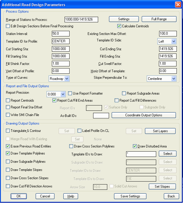 In the Process
Options section, the Range
of Stations to Process field sets the range of station that
you want to calculate. Each time you use this command, the existing
grade (.SCT) file is scanned and the range in the edit box is set
to the minimum and maximum stations in the file. If you change the
station range, you can click the Full Range button to restore the
default full range of stations.
In the Process
Options section, the Range
of Stations to Process field sets the range of station that
you want to calculate. Each time you use this command, the existing
grade (.SCT) file is scanned and the range in the edit box is set
to the minimum and maximum stations in the file. If you change the
station range, you can click the Full Range button to restore the
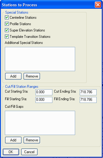
default full range of stations.The Settings button will interpolate additional existing cross sections (internally) and create final cross sections at special stations like profile high and low points, profile transition stations for PVC and PVT, key centerline points like PC's and PT's, and superelevation and template transition points and any user-defined special stations. These additional station improve volume calculations.
Volumes are calculated using end areas between the range of
stations. Also under the Settings button, there are controls
for the cut/fill starting and ending stations. Instead of cutting
off the volumes exactly at this range, the Ending and Starting
Stations for Cut and Fill can be used to have the volume taper from
zero at the specified Starting Station to the volume at the first
station in the range. Likewise the Ending Stations can be used to
taper the volume from the last station in the range to zero at the
specified Ending Station. You can also specify cut/fill gaps to
stop the end area volume calculations over the station range of
that gap. This applies in cases like a bridge.
 The Edit Design
Sections Before Final Processing does just that. You can
review and edit the final sections in the spreadsheet with graphic
view editor similar to the Input-Edit Section File command. For
example, you can change the tie slope as selected stations. After
making these changes, the modified final sections are used for the
rest of the road design process including earthworks and drawing
output.
The Edit Design
Sections Before Final Processing does just that. You can
review and edit the final sections in the spreadsheet with graphic
view editor similar to the Input-Edit Section File command. For
example, you can change the tie slope as selected stations. After
making these changes, the modified final sections are used for the
rest of the road design process including earthworks and drawing
output.
The Station Interval and
Existing Section Max
Offset buttons are ghosted if the existing surface is a set
of cross sections. If there is no existing surface, or the existing
surface is a grid, TIN or FLT file, then you must enter the Station
Interval to generate sections along the centerline. Besides the
stations at interval, sections can be created at special stations
as specified under the Settings button. The Existing Section Max Offset controls
the max left and right offsets for generating the existing sections
when the Existing Surface is defined by a triangulation file. This
offset needs to be set far enough for the final sections outslopes
to tie into existing. On the other hand, keeping this offset fairly
close to the tie point will help make processing run
faster.
The Calculate Centroid option applies to centerlines
containing curves. The centroids of the cuts and fills will be
computed, and the radius to these centroids will be calculated.
Then the effective interval will be computed between cut and fill
centroids. In this way, in a tight curve where fill is concentrated
to the outside of the curve and cut is concentrated to the inside
of the curve, fill will be increased and cut will be reduced. This
also increases the accuracy of volume calculations.
The Use Takeoff Strata
option uses the strata surfaces created in the Takeoff module to
report the strata cut volumes both for the total strata volumes and
the strata end areas per station. This method allows for unlimited
strata definitions with advanced modeling techniques including
Kriging and Inverse Distance to model strata surfaces. In Takeoff,
the Drillhole/Strata Settings command is where you define the
strata names and modeling methods. Next, the Place Drillhole
command creates the drillholes. Once the drillholes are entered,
use the Make Strata Surfaces command to build the strata surfaces
which are stored as TIN files and associated with the current
drawing.
The Template ID for Profile allows the profile grade to be applied to another template ID point other than the centerline. This feature might apply, for example, to a 2-lane road that will eventually be part of a 4-lane road being built in stages. The first-stage, 2-lane road would be fully symmetrical and designed around the crown of the road, but the template profile might be one of the edge of pavements. You can specify the template ID (e.g. EP), and whether the left or right side ID should be used to apply the profile grade.
The Shrink and Swell Factor edit boxes allow you to specify a value that the volume calculated will be multiplied by. If you specify any number other than one an additional report showing accumulated adjusted volumes and differences will be produced.
The Vertical Offset of Profile edit box will place the template at the profile grade as raised or lowered by the entered offset. The Horizontal Offset of Template will shift the template left or right on the centerline by the specified amount. Use a positive value to offset to the right and use a negative value to offset left. This option is useful, for example, when one side of a divided highway is built years before the other side is to be started. In this case, you could define a normal template with a crown in the middle, but would enter a horizontal offset from the crown of the road to the actual centerline of the divided highway.
The Slope Perpendicular
To option defines the slope projection method. The
centerline method creates the template cut/fill slopes
perpendicular to the centerline. The Slope Direction method
accounts for the slope of the profile and makes the final surface
to match the template cut/fill slope. For example, if the profile
is at a 10% slope and the fill slope is at 2:1, then the Centerline
method would create fill slopes that are 2:1 perpendicular to the
centerline while slightly steeper (1.96:1) for the actual slope
that goes in the slope direction with the effect of the profile.
For the same case except with the Slope Direction method, the
resulting slope perpendicular to the centerline is less steep
(2.04:1) while the actual slope in the slope direction is exactly
2:1.
The Report and File Output
Options include settings for reporting final coordinates (if
specified in the previous file output dialog), as well as special
features.
The Report Precision controls the number of decimal
places.
The Use Report
Formatter option allows you to customize the fields to
report and their order. It also can output the report to MS Excel
or databases.
The Report Subgrade Areas option will include an additional line in the report for the end area of each subgrade material.
The Report Centroids toggle controls whether the shift in
the cut or fill centroid radius shift will be included in the
earthworks report.
The Report Cut/Fill Text option greatly expands the size
of the report by presenting the cut and fill end areas at each
station. A sample of the cut/fill text report is shown below.
Volumes by end area method are presented between each line
containing station and end areas of cut, fill and optionally
rock.
Station   Cut(sf)  Fill(sf) Rock(sf) Interval  Cut(cy)  Fill(cy)  Rock(cy)

3+00.00   0.00     101.07   0.00

                                     50.00     313.78    93.58     0.00

3+50.00   338.88   0.00     0.00

                                      6.09      80.93     0.00     0.00

3+56.09   379.10   0.00     0.03

                                     43.91     824.60     0.00    31.84

4+00.00   634.92   0.00    39.12
The Report Cut/Fill
Differences option will report the cut/fill ratio and
balance at each station.
The Report Cumulative Cut/Fill
Differences option will report the running totals of
cut/fill at each station.
The Report Final Station-Offset option will create a report of the final section offset-elevation data in row-column format. The station and profile grade are shown on the left followed by columns of offset and elevation for each data point. There are options to report the surface points only, the subgrade points only or filter the points by ID.
Write SMI Chain File creates a chain (.CH) file that contains the centerline, profile and template data for SMI Construction V.
The As-Built IDs to Use option applies only if you have specified an as-built section file as one of the inputs in the previous dialog. Consider a normal road template with 20 feet to edge of pavement (EP) and 10 feet more to shoulder (SH). Going further, assume that when you run this template, it does a fill condition on the right and creates a TIE point. If you wanted to conform the template to match a wider section of road at certain stations, you could edit the output file of a normal run (using Input-Edit Section File) and create new offsets and subgrade points for widening and even force a trapezoidal ditch in cut, as shown in the entries below:
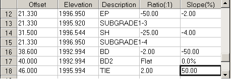
Because all the other offsets to the left match by default, this editing will force the template to conform from offsets 21.33 right to the tie at 46 right. As you try different design template or other changes in Process Road Design, this as-built information would hold for the specified station. Alternately, you could edit the final cross section directly in Input-Edit Section File. Note that you can use distinct, new ID points like BD2 which are not found in the template file, and they will be created if part of the as-built cross section file, and if referenced as As-Built IDs to Use. This As-Built method works best when inserting controlled section defined from TIE left to TIE right, which get inserted as completed sections in a run of Process Road Design.
The Output CRD File options apply when a Output Coordinate File is specified in the first dialog. These options allow you to output any combination of template surface, subgrade, ditch and berm points. The Output CRD To Use Sta-Off Desc option sets whether to include the station and offset in the description for each point. Here are example coordinates for station 0+90:
PtNo. North(y)  East(x)   Elev(z)  Description

 122  189497.42 611730.32 90.01    TIE 0+90.00L53.65

 123  189461.43 611733.72 108.09   SHD 0+90.00L17.50

 124  189457.45 611734.09 107.93   CURB3 0+90.00L13.50

 125  189456.95 611734.14 107.93   CURB2 0+90.00L13.00

 126  189456.95 611734.14 107.09   CURB1 0+90.00L13.00

 127  189455.96 611734.23 107.09   EP 0+90.00L12.00

 128  189444.01 611735.36 107.33   CENTER 0+90.00R0.00

 129  189432.06 611736.49 107.09   EP 0+90.00R12.00

 130  189431.07 611736.58 107.09   CURB1 0+90.00R13.00

 131  189431.07 611736.58 107.93   CURB2 0+90.00R13.00

 132  189430.57 611736.63 107.93   CURB3 0+90.00R13.50

 133  189426.59 611737.00 108.09   SHD 0+90.00R17.50

 134  189412.18 611738.36 100.85   TIE 0+90.00R31.97
The Drawing Output
Options bottom section of the Additional Earthworks
Parameters dialog contains output options which are only available
when a centerline file is specified.
The Triangulate &
Contour option will automatically run this command after
Process Road Design is done to create the final contours.
Triangulate & Contour uses the template 3D polylines to model
the final surface, and the disturbed area polyline is used as the
inclusion perimeter for the contours. With Triangulate &
Contour clicked on, the Setup button becomes active. Picking
Setup brings up the Triangulate & Contour settings including
the contour interval and whether to draw 3D Faces. Also under
Setup, there are controls for the colors of the 3D Faces for each
template break point. With Triangulate & Contour active, Draw
Template Polylines and Draw Disturbed Area Polyline are
automatically turned on. The Merge Road With Existing option
combines the road design triangulation with the existing ground
surface and stores the resulting triangulation in the file
specified with the Set button. This option is available when the
Existing Surface is a triangulation file and the Triangulate &
Contour option is active.
The Erase Previous Road
Entities option will erase any entities from the drawing
that were created in a previous run of Process Road Design using
the same design files. This option allows you to easily re-run
Process Road Design and update the drawing entities after changing
one of the road design files.
The Draw Cross Section
Polylines option will create 3D polylines perpendicular to
the centerline with each template break point. The interval of
these cross section polylines is determined by the station interval
of the Existing Sections.
The Draw Template
Polylines option will create 3D polylines parallel to the
centerline by connecting common template point IDs. For example, a
template ID could be EP which this option would use to create 3D
polylines for EP on the left and right of the centerline. Which
template point IDs to connect in set under Template IDs to Draw. Setting this to
an asterisk (*) will plot all the template break points. The
Select button shows cross
sections of the final templates for graphical selection of the ID's
to draw.
Likewise, the Draw Subgrade
Polylines option will create 3D polylines parallel to the
centerline for the specified subgrade breakpoints.
The Draw Disturbed Area
Polyline option will create a polyline perimeter that
represents where the cut/fill slopes tie into the existing
ground.
Draw Template Slopes
creates slope arrows parallel to the centerline at the specified
template ID's. For example, this option can be used to show the
slope direction and amounts along the template flowline. The style
of the slope arrows is set under the Set Slopes button at the bottom of the
dialog.
Draw Cross Section Slopes
create slope arrows perpendicular to the centerline at the
specified template ID's. For example, use this option to show the
cross section slope of the pavement lanes. The cross section
interval is controlled by the station interval under Process
Options. The style of the slope arrows is set under the
Set Slopes button at the
bottom of the dialog.
Label Profile On
Centerline creates labels in plan view for the profile
stations, elevations and slopes as well as high and low points.
This option has the same functionality as the command by the same
name in the Profiles menu.
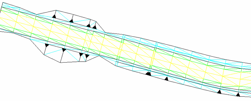
The Draw Cut/Fill Direction Arrows option will draw arrow
indicators for cut or fill slope direction. The arrows are drawn in
plan view and usually are drawn together with the Draw Disturbed
Area and Draw Cross Section Plines options. Cut arrows start from
the disturbed area limit and point towards the centerline. Fill
arrows start from the base of the fill slope and point away from
the centerline. The Solid Cut Arrows option chooses between
solid fill or wire-frame cut arrows. These arrows, especially when
drawn as solid cut arrows, help distinguish cut and fill at a
glance, when in plan view. In the example below, fill from a berm
is shown at the left and cut down to a ditch is shown at the right.
The arrows will only draw if there is enough dimension in the cut
and fill to fit the entire arrow. So the cut and fill arrows reveal
the deeper cut and fill zones.
Road Design Files dialog: Choose the design files
Additional Road Design Parameters
Road Design Report dialog
Trim existing contours inside
disturbed area (Yes/<No>)? Y This prompt appears
if Triangulate & Contour is on. This option will trim polylines
with elevation that cross the disturbed area perimeter for the
road.
Join final contours with existing (<Yes>/No)? Y
This prompt appears if Triangulate & Contour is on. This option
will join the final contours with the existing contours where they
join at the disturbed area perimeter.
Portion of Earthworks Report:
Template File> C:\DATA\simo2.tpl

Profile File> C:\DATA\rd.pro

Existing Section File> C:\DATA\simo2.sct

Centerline File> C:\DATA\simo2.cl


Processing 0+25.000 to 7+51.152

Total Cut : 800563.177 C.F., 29650.488 C.Y.

Total Fill: 1554948.266 C.F., 57590.677 C.Y.


Station  Cut(sf)   Fill(sf) Interval  Cut(cy)   Fill(cy)

0+25.000 4407.456  0.000

                            25.000    4784.266  0.000
0+50.000 5926.559  0.000

                            25.000    5535.921  0.000
0+75.000 6031.029  0.000

                            25.000    4840.888  0.000
1+00.000 4425.290  0.000

                            25.000    3432.528  0.000
1+25.000 2988.971  0.000

                            25.000    2713.262  3.362
1+50.000 2871.676 7.262
Portion of Final Station-Offset Report:
Final Surface Section Report

STATION      P.G.

2+50.000     1013.444 59.619 18.000 12.000 0.000 12.000

             992.634 1013.444 1013.204 1013.444 1013.204

2+75.000     1015.059 65.772 18.000 12.000 0.000 12.000

             991.173 1015.059 1014.819 1015.059 1014.819

3+00.000     1016.499 71.547 18.000 12.000 0.000 12.000

             989.725 1016.499 1016.259 1016.499 1016.259

3+25.000     1017.764 76.733 18.000 12.000 0.000 12.000

             988.398 1017.764 1017.524 1017.764 1017.524
 Existing Contours and
Centerline
Existing Contours and
Centerline
 3D template polylines,
disturbed area perimeter polyline and final contours
3D template polylines,
disturbed area perimeter polyline and final contours
 Template polylines and
final contours viewed in 3D using Viewpoint 3D command
Template polylines and
final contours viewed in 3D using Viewpoint 3D command
Review of 3 Methods of Transitioning Templates using Process Road Design
The 3 methods of template transitions and super elevation
are:
(1) Template Transition and/or Super Elevation Files
(2) Template Point Profile and Template Point Centerline files
(3) Template Series file which transitions between multiple, named
templates.
Road widening and lane transitions can be handled by all 3 methods. Special ditches are best handled by method (2), Template Point Profile and Template Point Centerline, especially since Template Transition files only work with lanes or portions of roads defined by the Grade button in Design Template. Template Transition files do not apply to cut and fill segments, unless they are designed as fixed features using the Grade button. Super elevation can often be handled by method (1) or method (3). Bear in mind that new lanes or template elements that emerge and then disappear need to exist as template ID points in all referenced templates, using all 3 methods. These template ID points can be set to 0.001 units from adjacent template points, then "told" to emerge and widen as new lanes with distinct slopes appear. The program will not transition templates that don't share common template ID points.
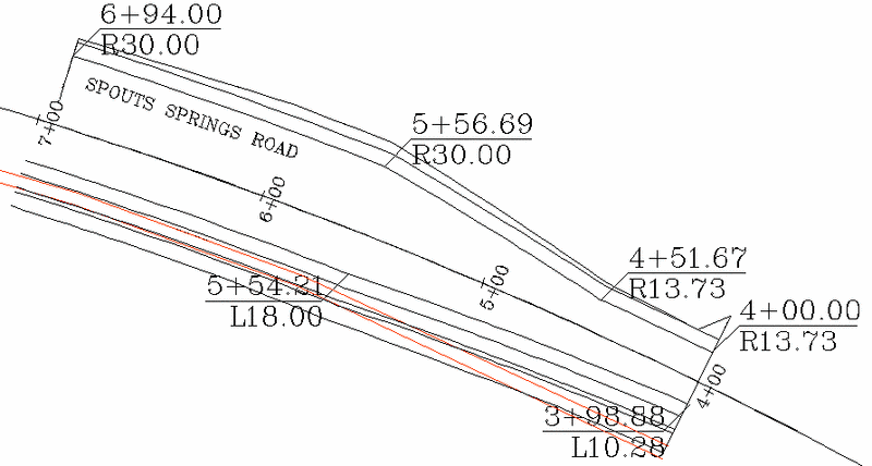
This deceptively easy looking example below might be approached by a combination of methods 1 and 2. For method 1 to apply (template transition), the slopes of the pavement lanes must be maintained according to the template definition from centerline to outside lane. The ditch portion will be handled by method 2 (template point centerline).
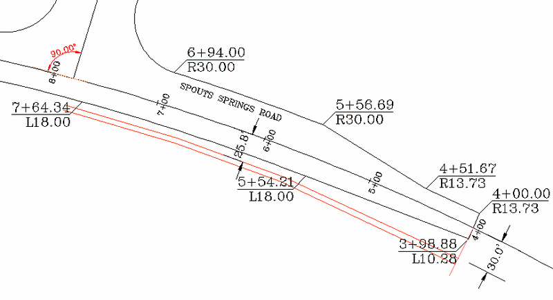
Assume Spouts Springs Road is a hillside road with a ditch cut
on the left side and fill on the right side. The trapezoidal ditch
is shown. We will design only from station 4+00 to station 6+94
where the intersection begins. The standard template of 10' left
lane and 10' right lane might appear as shown below:
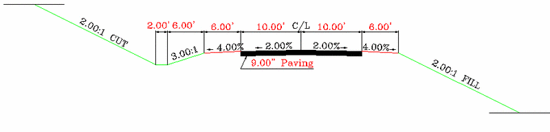
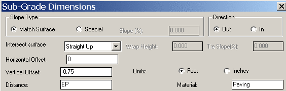
Note that if lanes are designed to expand, its important that
the subgrade (9" of paving, shown above) be defined as following
the ID, and should not be set to a fixed distance. The "EP" ID is
used in the dialog below (top of subgrade dialog within Design
Template) for this example.
The right hand portion of this example would be entered as follows:
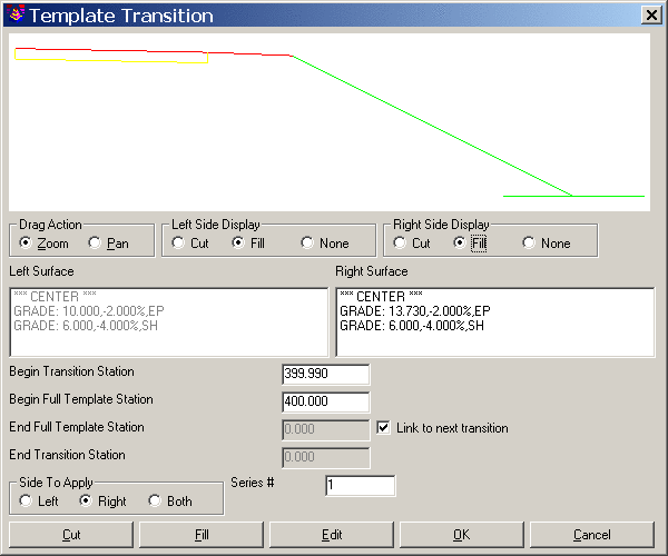
When you click "Add" within the Template Transition main dialog, you are presented with the above screen. Template transitions require that you specify the correct side of the road in the lower left, then click the Grade or lane to alter, which is the first lane on the right, which is set to 13.73 according to the plans. To make sure the lane is fully expanded from the standard 12 to the 13.73 at station 400, it is necessary to set the "Begin Transition Station" to something less than 400, as shown. Then if this "expanded" lane width does not transition back to standard 12 width, but changes again, you must click on "Link to next transition" and leave the "End Full Template" and "End Transition" stations blank. Then you click "Add" again for the final segment, which would be entered as shown:
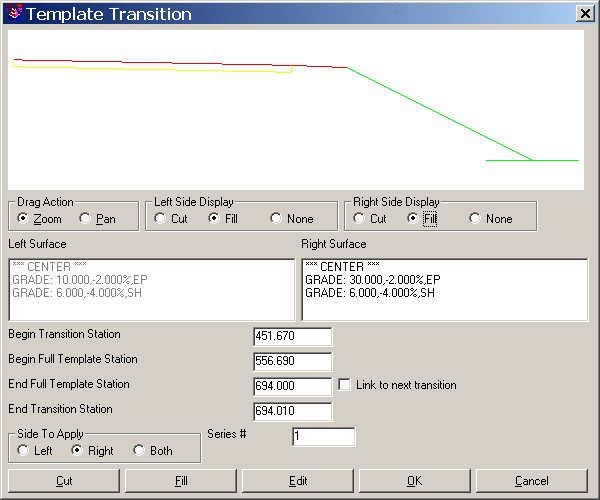
First, you specify "Side to Apply" as "Right", then click the pavement lane and edit it to 30', as shown above. Referencing the plan view drawing for Spouts Road shown above, you transition from station 451.67 to the new 30' road lane width at station 556.69 and hold that to the "End Full Template Station", which is 694.00. Then you can enter an "End Transition Station" just past the end of the key station range, which internally would transition the template back to a standard width of 12' at 694.01 (a moot point as the end of the project is station 694 for this exercise). The key to template transition is that it is designed to transition from normal to expanded or reduced dimension, then transition back to normal. It is ideal for use in passing lanes that appear and then transition back, but requires use of "Link to next transition" to handle a sequence of lane width changes as above. Therefore, where lane widths change often, and don't transition back to the normal template lane width, it is often best to use Template Point Centerline as the method of lane transitioning. We will apply that below to the ditch line.
When the template transition process is repeated for the left driving lane, you obtain a final Template Transition dialog as shown here:
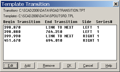
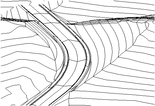
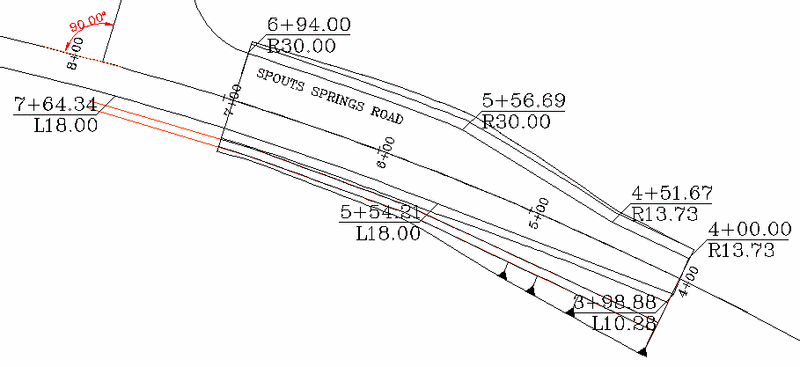
For the left side, the first screen just starts things up by establishing 10.28 as starting left side dimension, then the "Link to next transition" option is used, and the width of 18 is entered, transitioning to 18 at station 554.21 and holding that to an end station of 764.34, transitioning "back" to 12 at the fictitious 764.35, well beyond the 400 to 694 station range of interest. When this template transition file is run in Process Road Design and Triangulate & Contour is turned on within Process Road Design, the output clearly shows that the lane transitions have followed the lane expansions correctly:
However, it is easy to see that the "design ditch" on the left side of the road, at 2' wide, did not conform to the special ditch which hugs the shoulder at station 7+00 but transitions to further off of the shoulder at 4+00. This special ditch is best handled with Template Point Centerline. To complete the special ditch design, use Polyline to Centerline File on both ditch polylines, calling the inside polyline BD1.CL and the outside polyline BD2.CL, as a reference to the ditch IDs, BD1 and BD2. You can give them a starting station of 0. The stationing of the ditch polyline does not matter, since only the coordinates of the centerline in the command Assign Template Point Centerline are used to determine the template ID position. Within Assign Template Point Centerline, Add each of the ditch sides as shown:
Note that if the ditch always exists on the left side, the ditch
grades can be defined using the Grade button in Design Template,
rather than using the Ditch feature within the Cut button. For
final results, run the Process Road Design command using a
combination of the Template Transition File and the Template Point
Profile.
The end result is a final drawing that uses the Template
Transition file to create the correct edge of pavement and uses the
Template Point Centerline file to track along the correct ditch
polylines. This is shown below in the final drawing of the 3D
polylines generated by Process Road Design:
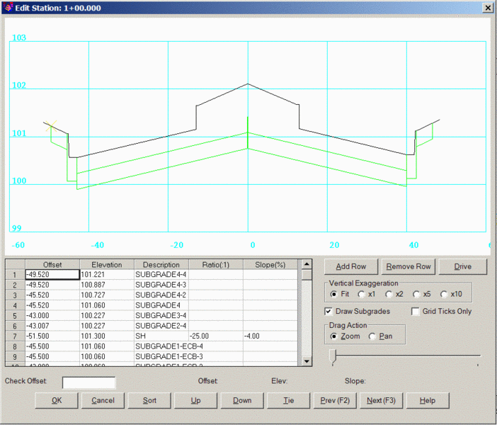
The actual slope to the ditch on the left is held at the design of 3:1, or whatever exists within the template from shoulder (SH) to base of ditch (BD1) in cut. Shown below in the Input-Edit Section File screen editor is station 6+50, where the ditch is designed very close to the shoulder:
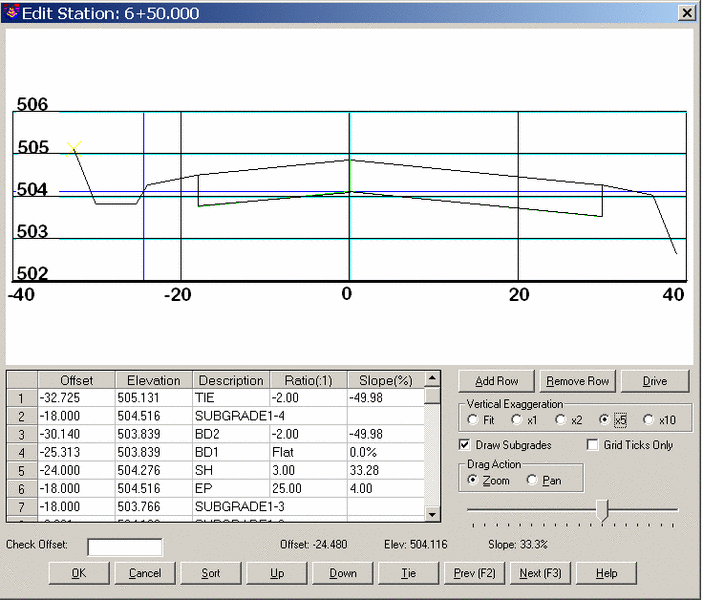
Note that the distance from BD1 to BD2 is irregular, based
entirely on the plan view offset of the ditch polylines. Note also
that BD1 to SH is 3:1, holding the defined slope. (The cursor
position also can be used to verify slope of any portion of the
section in "real-time".) Finally, note that the subgrade
follows the widening and irregular position of the pavement lane EP
for both left and right sides, since the subgrade offset from
centerline was defined as EP.
Although superelevation can be handled by use of superelevation
files, for most simple applications (2-lane roads in particular), a
single curve with superelevation can be handled by a template
series file, using only 3 templates: normal crown, reverse crown,
full super. This is illustrated below, for a typical 2-lane road
template:
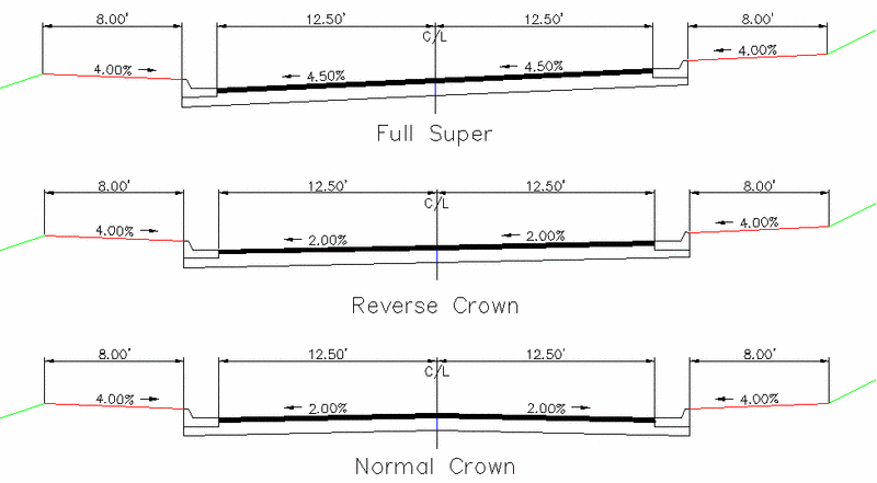
The actual Template Series File will consists of 6 entries for
one curve: Normal, Reverse, Begin Full Super, End Full Super,
Reverse, Normal. You would only need to make one extra
template, for simple roads, for every additional curve, for the
full super condition, since normal and reverse crown remain the
same. Note that the curbs, even on the high side, can be designed
to slope downward and catch the shoulder drainage in Design
Template by use of "special slope" of -1% in the curb design, or by
entering a value for the added "Drop" across the gutter portion.
Both methods create a downhill slope to the face of curb. So the
above project might be designed as shown below in the Input-Edit
Template Series command:
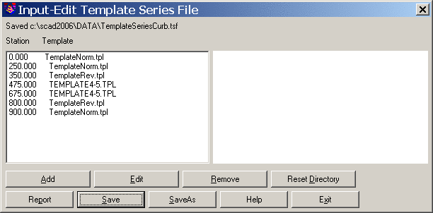
Note that beginning and ending stations are not necessary. If station 0.00 was omitted, Process Road Design would use the normal template in any case from station 0 to 250. Similarly, Process Road Design will use the normal template going forward from station 900 automatically.
Review of 2 Methods of Matching Portions of Existing RoadsThere are two main techniques for tying new template designs into existing roads, which may apply to road expansions, urban re-paving, grade improvements and other renovation projects. As more and more roadwork involves road improvement rather than new road development, these techniques become more useful and critical to master. The two techniques are: (1) Use of Template Point Profile and Template Point Centerline files to match existing conditions on portions of roads that do not change, and (2) Use of the "As-Built" cross section feature as one of the input files. An advantage of the As-Built method is that you can insert section points with special IDs for special features, whereas the Template Point Profile and Template Point Centerline methods must follow template IDs that are found in the original, main template design file. But the Template Point or "string" method allows for calculating sections at any interval, while the As-Built section method will revise final sections only at stations found in the As-Built section file.
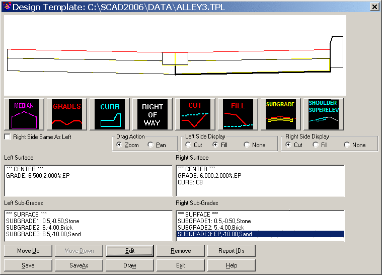
Consider this alley-way, which consists of a Belgian block style curb (no gutter) that is already in place. The plans are to remove a crowned asphalt alleyway and put in a bricked alleyway on sand, with a central, "depressed" rock drain of 1' width, to avoid water draining against buildings that abut the alley. But the design must match an existing "Belgian block" style curb on the right side of the road, which will not be removed.
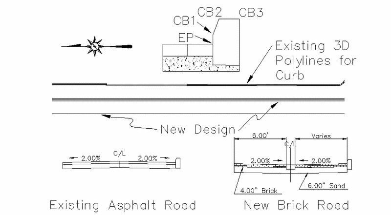
There is a new profile design involved, and a new template. However, the right side of the template will meet the exact grade and offset of the in-place curb, which has been surveyed as back of curb (CB3). Then the command Offset 3D Polyline was used to create the face of curb at EP=CB1, and to create the inside top of curb (CB2). Because of the symmetry and consistency of the curb, only the back of curb needed to be surveyed to hold the existing curb feature in place within Process Road Design. From that survey, the 3D Polyline for the EP is derived, which will be used for Template Point Centerline and Template Point Profile.
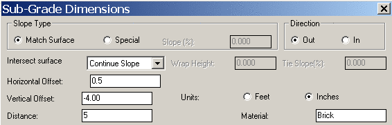
Features such as curbs and medians can be designed once within Design Template and then saved as curb or median files, then re-loaded and used in other templates, and applied to the left or right side of the template as desired. The central rock median of 1' total width can be constructed as two subgrades, one on the left side of 0.5' width and one on the right side of 0.5' width. The brick portion can be designed as a 4" thick subgrade as shown below. On the left side, you would need to use the "Straight Up" method of closing the subgrade surface. On the right side, you can use "Continue Slope". When using Continue Slope, it is best to underestimate the length needed to contact the next surface (the right curb), so continue can do an "extend" and find it. If you make the length too long (e.g. 6', which catches the curb which itself tilts back -2%), the program will not trim and will draw the subgrade to the back of the curb. Note that the vertical subgrade depth can be entered as 4 or -4. Both are accepted.
Be sure to define the sand subgrade on the right side (lowest subgrade) to have a distance of EP, a flexible distance that follows the precise offset of the EP "ID", which will be assigned to follow the face of curb template point profile defined by CB1 above.
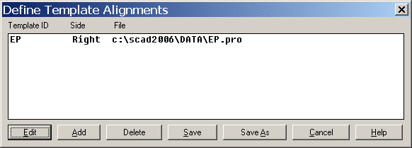
The next step is to set up the face of curb 3D polyline as a template point centerline and template point profile assigned to "EP". First you must do Polyline to Centerline File, pick the inner 3D polyline which is face of curb at proposed road level. Then you must do Profile from 3D Polyline and make a profile for the "EP". Then you assign this centerline and profile to the appropriate ID (EP) to force the curb to contact the correct curb position and elevation. The curb defined in the template matches the pattern of the in-place curb, so by setting EP to the correct template centerline and profile, the curb will "follow" at the correct position. The stationing used for the template point centerline is not critical to the calculation. However, the profile stationing much match and reference the centerline stationing. Therefore, when doing the command Profile from 3D Polyline, answer Yes to the question: "Station by another reference centerline [Yes/<No>]:". Making the Template Point Profile is always best accomplished by this method of Profile from 3D Polyline, referencing the design centerline. The Template Point Profile (and Template Point Centerline) would appear as shown here:
The files in Process Road Design would be set up as follows:

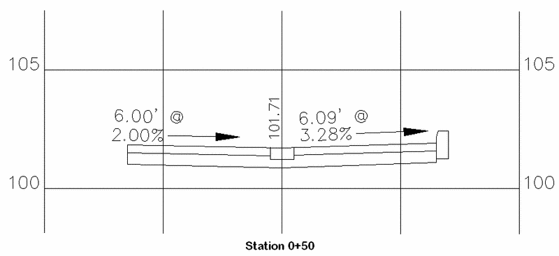
Note that no existing surface file is needed to compute final cross sections from as-built (straight wall on left of alley) to as-built (existing curb on right of alley). A final section is plotted below, showing the unique slope and lane distance determined by the as-built centerline and profile files that control the edge of pavement, and by extension, the curb, which continues with fixed dimensions from the edge of pavement.
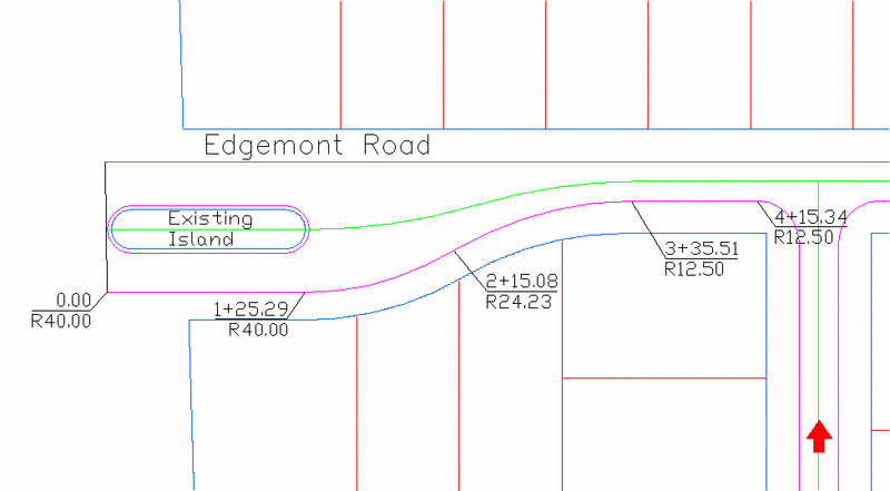
A second method of doing as-built road design is to use the as-built cross section method. Whenever as-built cross sections are specified as part of the input files in Process Road Design, and then referenced for use on the Additional Road Design Parameters screen within Process Road, those offset IDs that are referenced will be held. Any matching IDs or new IDs found in the as-built cross sections will be substituted for the designed IDs within the final sections. In the example below, it might be proposed to redesign Edgemont Road from a roadside ditch road to one with a curb and gutter as well as sidewalks. However, the designer might want to keep the existing central median, already curb and gutter with plantings.
This example raises the challenging issue of inserting special interior points with new IDs into a set of design cross sections, through a length of about 125 feet of road. If a cross section of the island is taken through station 1+00, it might have the following ID points:
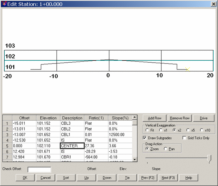
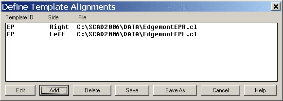
This cross section could then be part of an as-built cross section file (.SCT) which can be recorded at any desired station interval, the smaller the interval, the greater the accuracy. Now if the actual road template is defined as EP for edge of pavement and standard CB for curb, with CENTER for the centerline position, Process Road Design will substitute the As-Built File CENTER ID for the one calculated by the program, and will add in all the unique IDs from the cross section file, from -15.011 left to 15 right. Interestingly enough, this Edgemont Road example would also require a Template Point Centerline for the left and right edge of pavement, to pull the paving edge out to the expanded road dimension, which doesn't taper to normal until station 3+35.51. It would not require a Template Point Profile, so long as the road maintained a consistent design slope from centerline. When using Template Point Centerline, you need to turn the edge of pavement polylines into centerline files. Before doing so, test each polyline with the command Reverse Polyline (within Polyline Utilities under Edit) to verify that the polyline is drawn in the correct direction, as shown by the phantom arrows. The file Template Point Centerline elements might appear as shown:
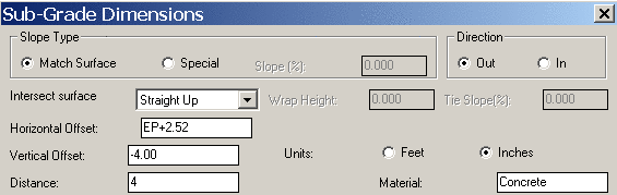
Be aware that a subgrade such as a concrete sidewalk, if it is to be placed behind the curb, must reference the curb or the edge of pavement ID for positioning, whenever the edge of pavement offset is changing based on use of a Template Point Centerline or As-Built cross section file containing duplicated IDs for edge of pavement. You can specify an offset for the sidewalk in the Subgrade option within Design Template, as shown below. The "2.52" offset was used to move past the tilting edge of the back-of-curb, which slightly exceeds 2.50.
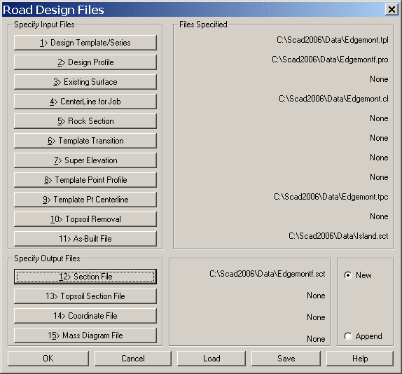
If the Island.sct file is the as-built cross sections, the entire input screen for the Edgemont Road project might appear as follows:
In the next dialog, fill in the descriptions for the section points in the As-Built IDs To Use field.

Here is the resulting output section file showing the
combination of the design template with the as-built section
points.
Example Divided Highway with Special Super Elevation Treatment
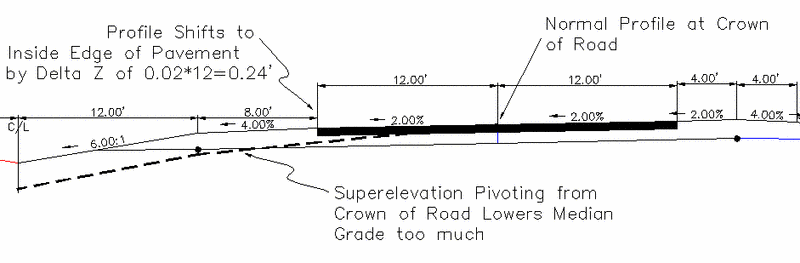
Divided highways such as 4-lane highways with a central depressed, grassy median are among the most challenging roads to define as templates, especially when accurate subgrade elevations and quantities are involved. Rules for superelevation and subgrade pivot points must be applied. And most divided highways do not use the centerline as the profile and require shifting the profile elevation to a specific template ID, like the inside edge of pavement or crown point for each side of the highway. This shifting occurs within Process Road Design. Furthermore, many highway departments have complicated rules for the profile grade. One such rule is that in superelevation, when the pivot lane reaches reverse crown, the profile moves from the crown of the road to the inside edge of pavement. Whatever the delta Z between the crown profile grade and inside edge of pavement profile grade is at reverse crown, this delta Z is subtracted from the profile grade and determines the profile of the inside edge of pavement from reverse crown through full super and back to reverse crown again. This typically improves drainage within the median portion, since a steep superelevation pivoting from the crown of the road can either reduce the median depth, or force the median too low. This is illustrated in the graphic below. Such challenging highways can be designed using special features within Design Template and Process Road Design.
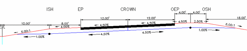
The divided highway template itself can be quite complex. Let's review the requirements of our template below, first left side, then right side, in superelevation of 4.5%.
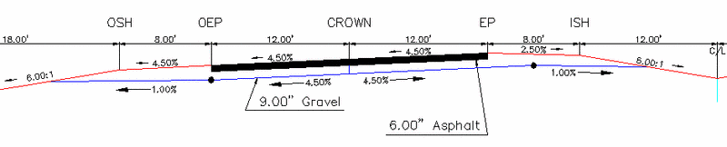
The main criteria for the design is that the pavement lanes are
12' wide, with 2% slope from the crown point in the middle (except
in superelevation). On the interior high side of superelevation
shown above, the grade breaks off at the EP or inside edge of
pavement, and the maximum algebraic difference is 7%. So at 4.5%
superelevation, the normal 4% downhill shoulder slopes instead at
7%-4.5%=2.5%, as shown. This part of the template behavior is
controlled by the Superelevation Shoulder button within Design
Template, with entries as shown here:
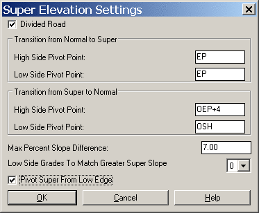
Note that the Super Elevation Settings dialog treats the "interior" of the road in the upper part, and the exterior of the entire road (like a 2-lane road) in the lower part. So the "Low Side Pivot Point" under the lower "Transition from Super to Normal" is where, walking from the middle of the road towards the left, super ends and normal slopes resume. That is set to OSH, or the outside shoulder position, the goal being to slope the full shoulder with the superelevation on the lower outside shoulder lane, then resume normal (non-super) slope at the 6:1 "recovery zone" slope. The entry of OSH as Low Side Pivot Point for Super to Normal controls that. In the upper part of the dialog, the inside "Transition from Normal to Super" sets the Low Side Pivot Point at EP. So at EP, walking from the template center left towards the left side of the road, normal ends at EP and superelevation begins. So the median upslope of 6:1 is normal, as is the shoulder, the super starts at EP. But because the 7% maximum percent slope difference is active, the shoulder can't remain at 4% but goes to 2.5% leading to the 4.5% superelevation. When super subsides to 3% or less, the shoulder would be normal at 4% as specified in the template design in this case.
Referring to the graphic above showing the left side of the divided highway, the gravel for the shoulder is shown running out to "daylight" on the outside recovery zone and on the inside median slope. However, to reduce quantities of stone, the stone runs at a uniform slope of -2% in normal crown, or matches superelevation, but pivots to 1% downhill at the outside OEP and 4' past the inside EP. This is accomplished through the subgrade entry dialog. First, the outside subgrade:
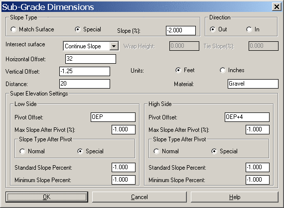
Note that the normal slope of the stone subgrade does not follow the surface but stays at the "special" slope of -2%, matching the surface always only beneath the asphalt portion within the pavement zone. For divided highways, it is always necessary to do at least 2 subgrades for each material: one from the crown or middle of the road "out" to the outslope (as above), and one from the crown or middle of the paved portion in to the interior. Since the crown of the road on each side of the highway is 32 feet left of the center depressed median position, the horizontal offset for the "out" position is 32. Enter the vertical offset as the entire distance from the horizontal offset down to subgrade bottom. In this way, any other thinner subgrades above are deducted from total subgrade quantities of the grade under consideration. If the goal is to "force" a -1% slope in both normal crown and superelevation, then set the Max Slope After Pivot(%) to -1%, and click "Special". Then set both Standard Slope and Minimum Slope Percent to -1%. This ensure that -1% will be used at the pivot offset of OEP, or as specified. Apply this to both subgrades ("in" and "out" from horizontal offset 32). If you simply entered -1% for the Max Slope After Pivot(%) and clicked Normal, slopes on the low side would break over to -1% but slopes on the higher side of each superelevation lane (beneath inside shoulder on the left, outside shoulder on the right) would continue on at the super slope and not break off. You must use the "Special" setting. The low side shoulder for the inside portion of the left side of the road is specified by the "In" subgrade, in this dialog:
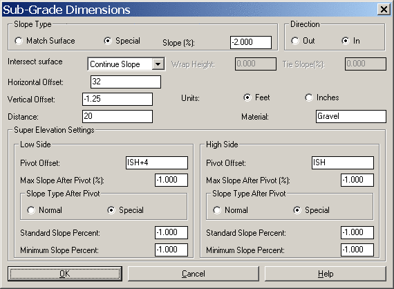
The pivot point for the subgrade on the inside left of the template is ISH+4, or 4 feet from inside shoulder to inside edge of pavement, the +4 being the direction walking out from the middle of the template in all cases. The right side of the template is shown next:
On the right side, the high-side subgrade pivot in the "out"
direction, walking from the middle of the road outward, is OEP+4.
On the right side, the high-side subgrade pivot in the "in"
direction is simply ISH, as shown. So the controls exist to specify
critical break points on subgrade and surface grades using Design
Template. Whether this is the best design can be debated, but the
controls are there to create surface and subgrade slope breaks and
grade changes.
Referring to the Super Elevation Settings dialog above, the key to
setting the superelevation of the divided highway to the inside
edge of pavement at reverse crown (minus the 0.24 delta Z from
profile grade to inside edge of pavement grade) is to click on the
option, "Pivot Super From Low Edge".
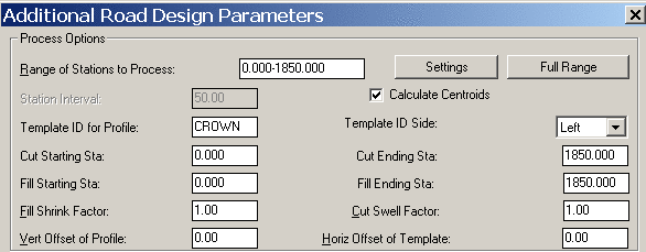
Now you must run Process Road Design, using this template, to
produce verifiable final cross sections. Set the Process Road
"Additional Parameters" dialog such that "Crown" (or whatever ID is
used for the center crown point on each side of the road) controls
the profile grade.
The final sections that are produced will shift the profile
grade to the inside edge of pavement from reverse crown to reverse
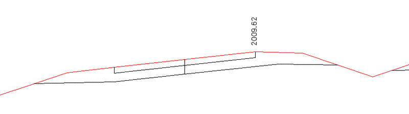
crown through superelevation, adjusted -0.24'. A final section is
shown plotted below as drawn using Draw Section File:
Pulldown Menu Location: Roads
Keyboard Command: eworks
Prerequisite: Profile file and template file