
Template Series is another method of widening lanes or causing
templates to change: direct template-to-template transitioning.
Using this command, you specify the station where one template
"ends" and the station where another template "begins", and the
program auto-transitions between templates.
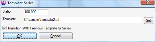
The Template Series is stored in a .TSF file and consists of a
sequence of template file names (.TPL) with stationing. The Design
Template command is used to create the .TPL files. The Template
Series can be used in commands like Process Road Design and Road
Network. In these commands, the template selection can be either a
regular template (.TPL) or the template series (.TSF).
For the transition to work optimally, the templates should share
the same IDs so that the program can connect the template 3D
polylines and transition between templates. If the templates are
distinct with separate, unrelated IDs, then by ending template1 at
station 500 (for example) and starting template2 at station 500.01,
a very abrupt transition can be accomplished.
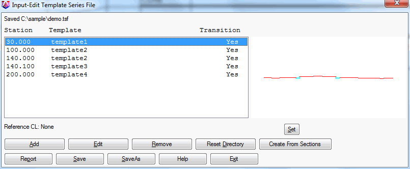
For a design with transitioning templates, the Template Series method is an alternative to the Template Transition method, a third method of Template Grade Table, and to a forth method of using Template Point Profiles and Template Point Centerlines, where a template ID "follows" a particular centerline and profile. One advantage of the Template Series approach is that it can be used to link different templates together, like non-curb and curb templates, as shown here in plan view:
For the above example, Template 1 applies from station 0+00 to
0+30, then transitions to Template 2 at 1+00 which has a wider EOP
distance. This transition occurs between stations 0+30 and 1+00.
Then the full Template 2 continues until station 1+40. Then
Template 3 starts with a curb replacing a standard EOP/Ditch
combination on the left side. So Template 3 would be set to begin
at 1+40.1, a short distance past 1+40. This template transitions
into Template 4 at station 2+00. Template 4 has a shorter middle
grade on the left side. You do not need to enter start and ending
templates at station 0+00 or after station 2+00. Therefore, the
dialog for this example might look as follows:
 Note that
you can run Process Road Design to review the design results in
plan view, with entry of only the Design Template/Series, the
Profile and the Centerline (items 1, 2 and 4 within Process Road
Design). You do not need existing cross sections to use Process
Road Design. If you process at an interval such as 10 over any
desired station range, you can output the Template Polylines and
verify the result in plan view. If no sections are found, the
program will process from edge of shoulder left to edge of shoulder
right, and omit cut and fill slopes. With the correct templates,
this would reproduce the plan view shown above.
Note that
you can run Process Road Design to review the design results in
plan view, with entry of only the Design Template/Series, the
Profile and the Centerline (items 1, 2 and 4 within Process Road
Design). You do not need existing cross sections to use Process
Road Design. If you process at an interval such as 10 over any
desired station range, you can output the Template Polylines and
verify the result in plan view. If no sections are found, the
program will process from edge of shoulder left to edge of shoulder
right, and omit cut and fill slopes. With the correct templates,
this would reproduce the plan view shown above.
 Pulldown Menu Location: Roads