Input-Edit Super Elevation
This command is an editor for super elevation stationing. The
super elevation data is stored in new or existing super elevation
(.SUP) files. When creating a new super elevation file, there is an
option to read a centerline file and build the super elevation
stationing based on the curves and spirals in the centerline using
AASHTO-based stationing or optionally, the Virginia DOT
method. The AASHTO calculations are based on the equations in
chapter 3 of the 2004 Green Book titled Geometric Design of Highway
and Streets. The length of the transition from normal crown to
superelevation will be automatically computed by the program using
either method based on the design speed and other settings, but the
user can control what percentage of this transition to and from
superelevation occurs in the tangent leading up to the curve or in
the curve itself. The Use Transition Curves option enables fields
for the transition curves at each super elevation grade break. For
example, if a normal grade is -2% and it starts changing at station
1+00 to reach 4% as station 2+00, then you could have a transition
at 1+00 to go from the constant -2% to the rate of change of 6%
over 100'. This transition curve will show up in the Draw
Superelevation Diagram similar to a vertical curve in Draw
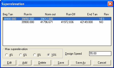
Profile.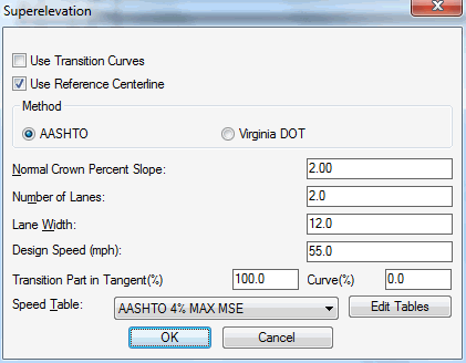 The main superelevation dialog displays a list of
each super elevation transition. These entries should be
sequentially entered from lowest to highest stations. To edit the
super elevation stationing, highlight the entry line and click
Edit. The Add button creates a new entry below the current
highlighted row or at the top of the list if no row is highlighted.
The Delete button removes the highlighted row from the list. The
Save button saves the super elevation file. To exit the program
without saving, click the Cancel button.
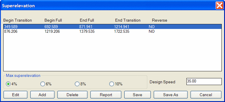
The main superelevation dialog displays a list of
each super elevation transition. These entries should be
sequentially entered from lowest to highest stations. To edit the
super elevation stationing, highlight the entry line and click
Edit. The Add button creates a new entry below the current
highlighted row or at the top of the list if no row is highlighted.
The Delete button removes the highlighted row from the list. The
Save button saves the super elevation file. To exit the program
without saving, click the Cancel button.
The super elevation stationing is entered in the Input/Edit
Superelevation dialog. The View Table button shows a table of the
super elevation slope for the delta angle and radius at different
design speeds. The Calc Super button calculates the slope of full
super given the design speed. The station entries are defined as
follows:
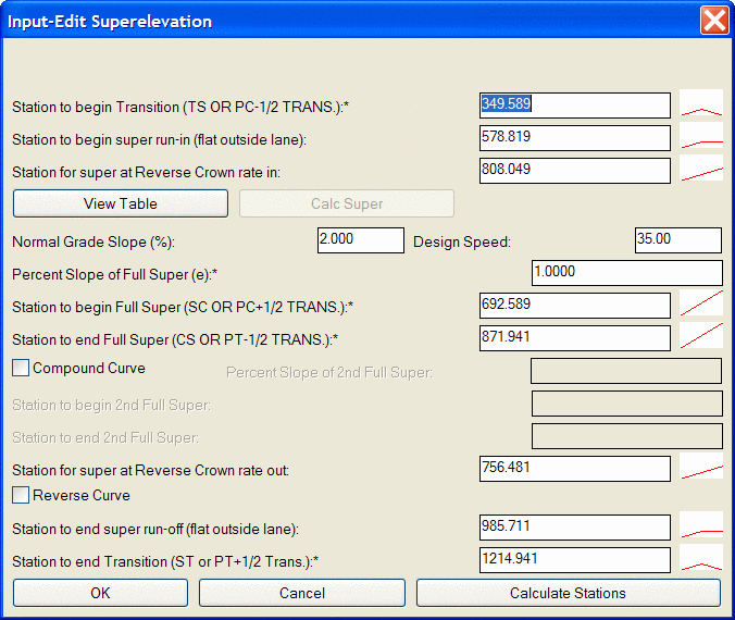
Station to begin
transition: where normal crown rate begins to transition
Station to begin super
run-in: where slope becomes flat
Station for super at normal crown
rate in: where slope equals negative of normal crown
rate
Station to begin full
super: where slope reaches full super slope
Station to end full super:
where slopes begins to transition from full super back to
normal
Station for super at normal crown
rate out: where slope equals negative of normal crown
Station to end super
runoff: where slope becomes flat
Station to end transition:
where slope returns to normal crown rate
Given these various Station settings, an unequal rate of change
can occur between any two stations. However, the program can
calculate the stations to set an even rate of transition, as long
as it knows the max superelevation, the normal crown slope and the
station to start transition, start full super, end full super and
end transition. The Calculate Stations button therefore
calculates the stations for begin run-in, normal crown rate in,
normal crown rate out and end super run-out. To calculate these
stations the values with an "*" must be entered.
The Compound Curve option allows you to specify a second
superelevation slope for a compound curve. In addition to
specifying the second slope, the starting and ending stations for
this slope must also be entered. The Reverse Curve option is
similar to the Compound Curve option. A typical Reverse Curve
is shown below in plan view and as it would appear in the summary
dialog:
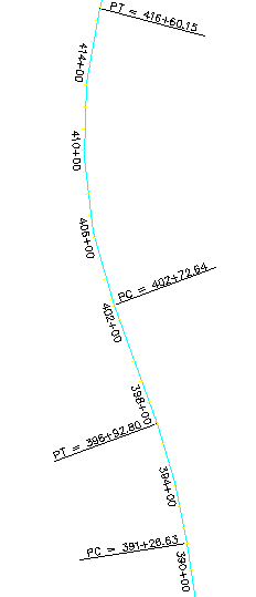
Station 399+00 is the "pivot" where superelevation left flattens
and turns into superelevation right.
Prompts
New or Existing Super Elevation File dialog
Superelevation File to Process Specify a superelevation
file.
Superelevation Editor dialog
Pulldown Menu Location: Roads
Keyboard
Command: super
Prerequisite: None