Design Template
This command creates a template definition file (.TPL file). The
template file can then be applied in the Process Road
Design, Road Network, Draw Typical Template, Locate
Template Points or Design Pad Template commands. The
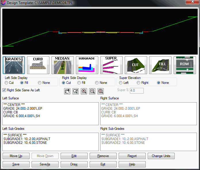
template is designed using the dialog shown below. The top portion
shows a graphic preview of the template as you create it. You can
choose whether to show cut or fill slopes on the left and right
sides. Also, you can choose whether to show the template in
superelevation. In the middle is a row of icons which are the
building blocks of the template. They can be chosen in any order by
picking on the icon. In the bottom of the dialog are four list
boxes that list the elements of the template. The surface elements
are listed in order starting from the center. The subgrades are
listed from top to bottom order. To add a template element,
highlight the position in the list above where to insert the
element. Then pick one of the element icons. To change the order of
an element, highlight the element and pick the Move Up or Move Down
buttons. The Edit button edits the dimensions of the highlighted
element. The Remove button erases the highlighted element from the
list. The Report button has two different report formats that
include just the ID's of the template elements or all the
dimensions of the template elements. The Change Units button allows
you to apply a scale factor to the distances in the template which
can be used to convert between English and Metric. The Import
Polyline button adds grades to the template from a selected
polyline. The Profile Delta Z applies a vertical offset to the
profile when the template is processed. This vertical offset
applies to a template that has an element at the profile position
that makes the template different than the profile grade. For
example, when the profile grade is along the centerline at the
pavement level and the template has a curb or median that is 0.5
above the pavement, then set the Profile Delta Z to 0.5 so that the
template matches the pavement grade after coming down from the 0.5
curb or median.
There is no limit to the number of surface or subgrade elements.
Note that there is a Right Side Same as Left option. When active
this option only requires template design for the left side and
will automatically mirror the design for the right side.
 The template surface can be
composed of three types of elements: medians, grades and curbs. The
median is a flexible closed figure defined in a clockwise
direction. Each median point consists of an X and Y offset. The
median must be closed and the program will automatically create the
closing segment. In the Median Design dialog, the median is shown
in the top display and bottom has a list of median points. The
display shows the median in magenta and the grade lines in and out
in green. For the display the grade in comes from the left and the
grade out goes to the right. The median must define the Grade In
point which is the point that ties into the incoming surface grade.
Also the Grade Out point must be specified for where the surface
grade continues out from the median. These Grade In and Grade Out
points emanate from the starting or "from" position in the
coordinate dialog where they are specified. Since a single median
must be placed on the left or right side (and is typically not used
symmetrically with right side same as left), you will need to
offset the template centerline one-half the median width within the
command Process Road Design in order to center the median. You will
also have to move the "C/L" designation, to obtain centering, when
using Draw Typical Template.
The template surface can be
composed of three types of elements: medians, grades and curbs. The
median is a flexible closed figure defined in a clockwise
direction. Each median point consists of an X and Y offset. The
median must be closed and the program will automatically create the
closing segment. In the Median Design dialog, the median is shown
in the top display and bottom has a list of median points. The
display shows the median in magenta and the grade lines in and out
in green. For the display the grade in comes from the left and the
grade out goes to the right. The median must define the Grade In
point which is the point that ties into the incoming surface grade.
Also the Grade Out point must be specified for where the surface
grade continues out from the median. These Grade In and Grade Out
points emanate from the starting or "from" position in the
coordinate dialog where they are specified. Since a single median
must be placed on the left or right side (and is typically not used
symmetrically with right side same as left), you will need to
offset the template centerline one-half the median width within the
command Process Road Design in order to center the median. You will
also have to move the "C/L" designation, to obtain centering, when
using Draw Typical Template.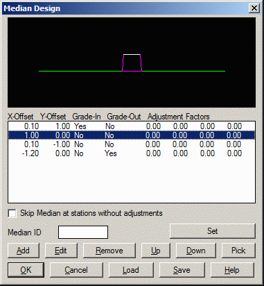 Using the
Load and Save buttons, medians can be saved and loaded with .MDN
files for sharing and re-use in other templates. The Up and Down
buttons change the order of the highlighted X/Y Offset record in
the list. The Pick button prompts to pick a closed polyline from
the drawing to define the median geometry. The Set button shows a
list of grade ID's from the current Template ID Library. The Skip
Median option creates the median only in the station range of
Template Point Profile or Template Point Centerline
transitions.
Using the
Load and Save buttons, medians can be saved and loaded with .MDN
files for sharing and re-use in other templates. The Up and Down
buttons change the order of the highlighted X/Y Offset record in
the list. The Pick button prompts to pick a closed polyline from
the drawing to define the median geometry. The Set button shows a
list of grade ID's from the current Template ID Library. The Skip
Median option creates the median only in the station range of
Template Point Profile or Template Point Centerline
transitions.
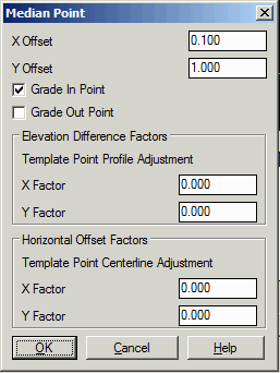
To enter the dimensions of the median, use the Add or Edit
button. The adjustment factors control how to apply Template Point
Profile and Template Point Centerline adjustments. For Template
Point Profiles, the program figures the amount of vertical
adjustment between the transition profile and the normal profile.
The amount of this vertical adjustment is multiplied by the
adjustment factor and then added to the X/Y Offsets of the median
point. Likewise, the program figures the horizontal adjustment
between the transition centerline and normal centerline for
Template Point Centerlines and applies this adjustment by the
factors to the offsets. These adjustment factors allow for dynamic
medians. For example, the height of a retaining wall could be
controlled using a Template Point Profile and the median points for
the vertical sides would have a Y Factor set to 1 to pick up the
full vertical adjustment and the median points for the top and
bottom edges would have a Y Factor of 0 keep those edges the
same.
 You can design a median for "mirroring" to create a
centered effect, as shown below. The only negative to this method
is the appearance of a vertical line in the median plot.
You can design a median for "mirroring" to create a
centered effect, as shown below. The only negative to this method
is the appearance of a vertical line in the median plot.
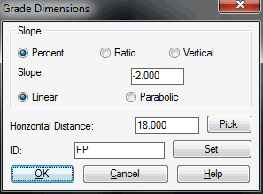
 Surface grades can be entered by
selecting the Grades icon which brings up the dialog shown.
Downhill slopes are negative and the Distance is the horizontal
distance. The slope can be specified in either Percent, Ratio or
Vertical format. The Vertical format is the actual elevation
difference. The slope type can be either Liner or Parabolic. The
Linear is a constant slope and the Parabolic gets steeper across
the grade until it reaches the full specified slope at the end of
the grade. The text ID serves 4 purposes: (1) The ID will be
applied as a description to all final template points generated in
the form of a coordinate (.CRD) file, (2) The ID can be used as a
design point, as in EP+5 indicating 5 feet or meters right of edge
of pavement, (3) Points of common ID may be connected by 3D
polylines as an output option of Process Road Design and (4)
Quantities can be generated with reference to the ID and material
(gravel, concrete, etc.) entered elsewhere within this command. The
Pick button prompts to select a linework segment or two points from
the drawing to define the grade slope and distance. The Set button
shows a list of grade ID's from the current Template ID
Library.
Surface grades can be entered by
selecting the Grades icon which brings up the dialog shown.
Downhill slopes are negative and the Distance is the horizontal
distance. The slope can be specified in either Percent, Ratio or
Vertical format. The Vertical format is the actual elevation
difference. The slope type can be either Liner or Parabolic. The
Linear is a constant slope and the Parabolic gets steeper across
the grade until it reaches the full specified slope at the end of
the grade. The text ID serves 4 purposes: (1) The ID will be
applied as a description to all final template points generated in
the form of a coordinate (.CRD) file, (2) The ID can be used as a
design point, as in EP+5 indicating 5 feet or meters right of edge
of pavement, (3) Points of common ID may be connected by 3D
polylines as an output option of Process Road Design and (4)
Quantities can be generated with reference to the ID and material
(gravel, concrete, etc.) entered elsewhere within this command. The
Pick button prompts to select a linework segment or two points from
the drawing to define the grade slope and distance. The Set button
shows a list of grade ID's from the current Template ID
Library.
 To add a curb, select the Curb
icon. The dialog box below appears where you can fill in the curb
dimensions. There are three curb types to choose from. The curb
dimensions can be specified in feet, inches or meters in metric
mode. The Smooth option will smooth the surface of the curb which
only shows when the template is applied in commands such as
Process Road Design. The Round option will fillet a curve at
the bottom and top of the taper using the specified Bottom and Top
Radius. The Integral/Separate option determines whether to draw the
front line of the curb to separate the curb from the subgrade. For
example, fully concrete pavements that contain a curb would be
drawn with the "integral" curb option. The Base Slope Type of the
curb can either be flat, set to the slope of the incoming grade or
set to a user-specified slope. For the Match Crown method, you can
use the Table option to define a lookup table of different curb
slopes for different crown grades. For cases with part of the curb
at a slope and part flat, you can use the Base Break Offset to set
the transition position between sloped and flat. The Target setting
for the slope controls which parts of the curb are sloped. The
Material name is used in the Process Road Design report. The
ID is a unique identifier for this element of the template and is
used for referencing the curb in other routines. The Direction
controls which way the curb faces. This Direction option is needed
for divided roads that have curbs facing both ways on either side
of the road.
To add a curb, select the Curb
icon. The dialog box below appears where you can fill in the curb
dimensions. There are three curb types to choose from. The curb
dimensions can be specified in feet, inches or meters in metric
mode. The Smooth option will smooth the surface of the curb which
only shows when the template is applied in commands such as
Process Road Design. The Round option will fillet a curve at
the bottom and top of the taper using the specified Bottom and Top
Radius. The Integral/Separate option determines whether to draw the
front line of the curb to separate the curb from the subgrade. For
example, fully concrete pavements that contain a curb would be
drawn with the "integral" curb option. The Base Slope Type of the
curb can either be flat, set to the slope of the incoming grade or
set to a user-specified slope. For the Match Crown method, you can
use the Table option to define a lookup table of different curb
slopes for different crown grades. For cases with part of the curb
at a slope and part flat, you can use the Base Break Offset to set
the transition position between sloped and flat. The Target setting
for the slope controls which parts of the curb are sloped. The
Material name is used in the Process Road Design report. The
ID is a unique identifier for this element of the template and is
used for referencing the curb in other routines. The Direction
controls which way the curb faces. This Direction option is needed
for divided roads that have curbs facing both ways on either side
of the road.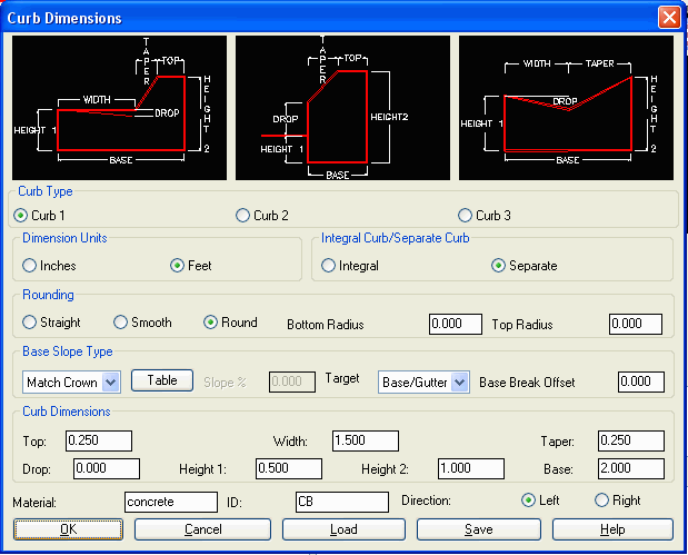
|

|
|
|
Straight & rounded curbs |
|

|
|

|
| Integral and separate curbs |
To specify cut treatment, pick the
Cut icon. There is room to specify up to five cut slopes which can
be slopes in series or slopes to use at different depths. In a
simple case of one cut slope, you can just enter the one slope
value and leave the depth and other slope boxes blank. For Slopes
in Series, each slope is used up to the specified depth until an
intersection with the ground. If the intersection is not reached by
the first slope, then the next slope continues from where the first
ended. If you have more than five slopes, pick the Repeat Slopes
option which will repeat the sequence of entered slopes until the
ground is reached. The Bench Between Cuts option allows you to
enter a bench width and percent slope to be inserted between each
cut slope. Besides running the cut slopes to specific depths, the
Cut To Section option can be used to have each cut slope intersect
a surface from a section (.sct) file. With Cut To Section on, the
Process Road Design command will prompt for these cut slope section
files. For example, this Cut To Section option could be used when
you have a cut bench that occurs at a set elevation but different
cut depths as the road profile changes. In this case, you could
create a section (.sct) file at this set bench elevation.
 The Pick buttons prompts to select a linework
segment or two points from the drawing to define the cut
slope.
The Pick buttons prompts to select a linework
segment or two points from the drawing to define the cut
slope.
The Tie to Set Offset forces the cut slope catch point to a
specified fixed offset. This offset can be relative to the
centerline or the template pivot point. This tie method can be used
when you want the cut slope to always tie into existing at a fixed
ROW offset.
The Force Fill option will make the template attempt to find a
catch point with a fill slope even when the pivot point is in cut.
You can specify the fill slope to use and the maximum depth for the
fill slope.
The Tie ID sets the description to use in the design section
file for the tie point. This is the same setting as under the Fill
Grades dialog.
The Load Ditch and Save Ditch functions allow you to save and
recall ditch grades to a .DIT file. This way to can make your own
library of ditch definitions.
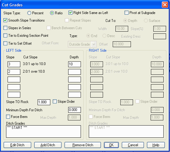
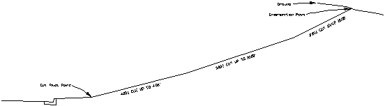
With Slopes in Series off, just one of the slopes is used
depending on the depth. For example, set the dialog as shown to use
4 to 1 slopes at depths up to 4 feet, 3:1 up to 10 and 2:1 if
deeper. The effect is 4:1 if shallow and, by contrast, 2:1 if the
fill is deep. The Smooth Transitions option will gradually
transition the slopes from one range to the next. In this example,
if the depth is 5 feet the slope will be between 4:1 and 3:1. The
graphic in the Design Template dialog will explicitly show slopes
in series versus individual slope depending on setting (shown below
are individual slopes, with slopes in series off):
 The Pivot at Subgrade
option will position the cut pivot point where the bottom subgrade
intersects the template grade. The ditch or upslope conditions will
then occur from this special subgrade "daylight" pivot point,
instead of from the outer shoulder surface pivot point. The Tie to
Existing Point will draw the cut slope from the cut pivot point to
either the outside offset-elevation or an offset-elevation point
with a specified description from the existing section file. This
method is used when survey crews take sections and designate the
specific slope tie points.
The Pivot at Subgrade
option will position the cut pivot point where the bottom subgrade
intersects the template grade. The ditch or upslope conditions will
then occur from this special subgrade "daylight" pivot point,
instead of from the outer shoulder surface pivot point. The Tie to
Existing Point will draw the cut slope from the cut pivot point to
either the outside offset-elevation or an offset-elevation point
with a specified description from the existing section file. This
method is used when survey crews take sections and designate the
specific slope tie points.
|
|
| Three
cut slopes in series |
The Slope to Rock applies in Process Road Design when using a
Rock Section File. There are two slope order modes for rock slopes:
Slope TO Rock and Slope FROM Rock. For the Slope TO Rock mode, the
cut slope will be the Slope To Rock up to the rock surface. After
reaching the rock surface, the regular cut slopes apply. For the
Slope FROM Rock mode, the regular cut slopes apply up to the rock
surface. Then from the Slope From Rock applies from the rock
surface to the ground surface.
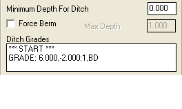
Ditch Grades can be inserted prior to the application of the cut
upslope. For curb and gutter roads, there is typically no ditch.
But for roads with drainage downhill to the outside and no curbs,
ditches are typically used in cut conditions. The Ditch Grades list
contains each ditch grade in order from the regular template. Any
number of ditch grades can be added by picking the Add Ditch
button. To create a V ditch, add just one ditch grade such as slope
ratio -1, distance 1. This makes one side of the V. The pivot point
for the cut slopes will be the bottom of the V and the other side
of the V will be made by the cut upslopes. For a ditch with a flat
bottom, you could have two ditch grades such as slope ratio -2,
distance 4 and then slope percent 0, distance 2. If a minimum depth
for ditch is entered, no ditch will be applied unless the cut
exceeds that depth. The Force Berm will apply the Berm (defined
using the Fill icon) in cut instead of a ditch up to a certain
depth of cut.
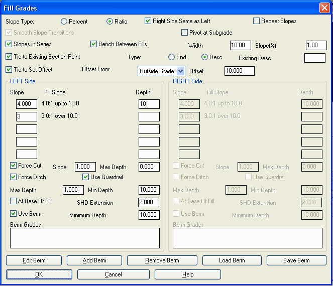 Fill treatment is similar to cut. Up to five slopes
for different depths can be specified. Slopes in Series and Smooth
Transitions work the same way as cut. Berm Grades are the fill
equivalent to Ditch Grades. Fill treatment does have some extra
options. Guardrail Expansion will extend the last template surface
grade the specified Shoulder Distance when the fill is greater than
the Min Depth. The Force Ditch option has two different methods to
apply the Ditch Grades from the cut definition. With "At Base Of
Fill" on, Force Ditch creates the ditch where the fill slope hits
existing ground. With "At Base of Fill" off, the Force Ditch method
applies the ditch grades from the template pivot point. The Minimum
Depth for Berm Grades will only draw the Berm Grades when the fill
depth is greater than the specified value. The Force Cut option
will make the template attempt to find a catch point with a cut
slope even when the pivot point is in fill. You can specify the cut
slope to use and the maximum depth for the cut slope.
Fill treatment is similar to cut. Up to five slopes
for different depths can be specified. Slopes in Series and Smooth
Transitions work the same way as cut. Berm Grades are the fill
equivalent to Ditch Grades. Fill treatment does have some extra
options. Guardrail Expansion will extend the last template surface
grade the specified Shoulder Distance when the fill is greater than
the Min Depth. The Force Ditch option has two different methods to
apply the Ditch Grades from the cut definition. With "At Base Of
Fill" on, Force Ditch creates the ditch where the fill slope hits
existing ground. With "At Base of Fill" off, the Force Ditch method
applies the ditch grades from the template pivot point. The Minimum
Depth for Berm Grades will only draw the Berm Grades when the fill
depth is greater than the specified value. The Force Cut option
will make the template attempt to find a catch point with a cut
slope even when the pivot point is in fill. You can specify the cut
slope to use and the maximum depth for the cut slope.
The Right of Way icon brings up the dialog shown which allows
you to specify whether to use a retaining wall to keep the cut/fill
slopes from crossing the right of way. The right of way data is
stored in a centerline file (.cl file) as stations and offsets for
the left and right sides of a centerline. When the retaining wall
option is active, the cut or fill slope will go at the design slope
up to the right of way and then the slope will tie into the ground
by going straight up or down. Without the retaining wall option,
the cut or fill slope will become steeper in order to tie into the
ground at the right of way. For example, if the cut slope is 50%
but this slope ties into the ground past the right of way, then the
slope will be modified to something steeper such as 65%. The Offset
ROW options will force the tie in the offset distance before the
right of way.

The Shoulder Super Elevation icon specifies where on the
template the slopes will transition between super elevation slopes
and normal slopes. The transition point is identified under Pivot
Point by the template id for the grade, curb or median. Note that
the pivot point can be specified as an ID plus a distance as in
"EP+2". Starting from the center, the template grades will be in
super up through this template segment. For example, based on the
template shown in the first dialog of this command, the EOP Pivot
Point the Super Elevation Settings dialog will create the first EOP
grade in super while the curb and grade S will be at normal grade.
The High and Low Pivot Point options allow for different transition
points depending on which side is raised by the super elevation.
The Max Percent Slope Difference is the maximum difference between
the super elevation grade and the normal grade at the pivot point.
For example with a Max Percent Slope Difference of 7%, if the super
elevation grade is 6%, then the slope after the pivot on the high
side will be -1% even if the normal design slope is steeper than
-1%. If the grades do not start from the center in super, then the
Divided Roads option can be used. With this option, the grades
start from the center as normal and then transition to super at the
Normal to Super Pivot Point.

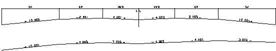
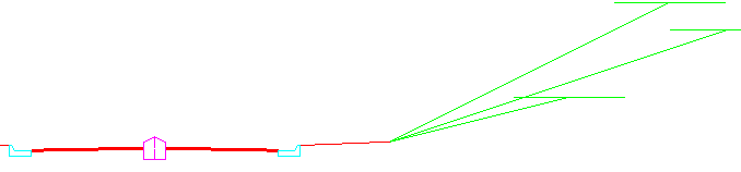
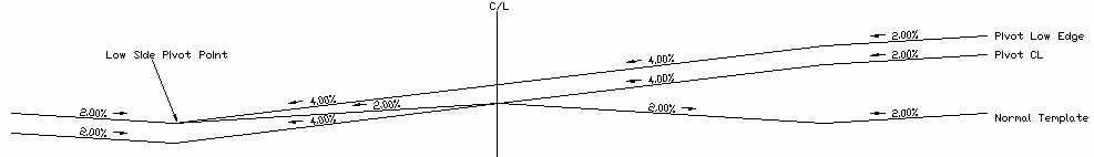
Here is an example of super elevation of 4% to the right for a
divided road with a Max Difference of 7%. The normal template is
shown above. The Normal to Super Pivot Point is MED and the Super
to Normal Pivot Point is EP. The result is that the EP segment is
in super and the SH and MED segments are at normal slope. On the
left, the SH segment is at the normal -10%, the EP segment is at
the super elevation slope of -4% and the MED segment wants to be at
4% but ends up at 3% because this meets the Max Difference
requirement. On the right side, the MED segment starts at the
normal -4%, then the EP segment transitions into the super -4% and
then the SH transitions back to normal which results in a 3% slope
because of the Max Difference requirement.
The Low Side Grades To Match Greater Super Slope option applies
to the template grades that are outside the super pivot. When the
super slope becomes steeper than these outside grades, then these
grades are adjusted to match the same super slope. You can set up
to two grades past the super pivot to adjust. For example, consider
a template where the super pivot is the EP grade and the next grade
is a SHD for the shoulder. If the SHD normal slope is -4%, then the
SHD will stay at -4% through the super transition until the super
becomes greater that -4%. So when the super is at -6%, the SHD will
also be at -6%.
The Pivot
Super From Low Edge holds the normal crown grade of the low side
edge of super and raises the rest of the template to match the
super slopes. Otherwise the profile grade at the centerline is
held.
To add subgrades click the SubGrades icon which brings up the
dialog shown. The subgrades are areas below the template surface.
There can be any number of subgrades stacked one below another or
side by side.
The subgrade starts from the surface at the distance from the
center set under Horizontal Offset. To start from the centerline,
enter 0 in Horizontal Offset. First the subgrade moves straight
down from this Horizontal Offset. The depth down is specified in
Vertical Offset in feet units or meters in metric mode. The
Vertical Offset normally should be set as a negative number. The
bottom of the subgrade then either moves away from or towards the
center depending in the Direction In or Out setting. The distance
to move is specified under Distance. The Slope Type for the
subgrade bottom can be either set to a specified slope or set to
match the grades of the surface. After moving the specified
distance, the subgrade will tie back into the template surface
either by going straight up, by continuing at the subgrade slope
until intersecting the surface or by wrapping around. The commonly
used "continue slope" approach will extend the slope until it hits
something (like a curb or another surface segment). It will not
trim. So if the pavement segment is 12 feet to a curb, it is better
to enter 10 and "continue slope" than to enter 12 exactly, as a
"tilted" curb may place the curb edge at 11.98' from the start of
the subgrade, causing the subgrade to go past face of curb and
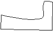
intersect back of curb. Also, for angled tie-ins of subgrade from
base of curb to the surface, such as the example shown below, be
sure the distance entered is less than what would intersect the
surface, so that the "extend" effect will create the intersect. In
this example, the first subgrade (asphalt) is "continue slope", the
second (gravel) is "straight up" and the third (gravel tie in
behind curb) is "continue slope".
 The
Material field is an optional description that is used in the
Process Road Design report.
The
Material field is an optional description that is used in the
Process Road Design report.
Special super elevation pivot points may optionally be
specified. The Pivot Offset allows the subgrade slope to break in
super elevation independently of where the surface grade breaks.
The subgrade will follow the super elevation slope from the
centerline to the Pivot Offset. Then after the Pivot Offset, there
are options to set the slope. The Min and Max Slope settings
restrict the subgrade slope. The Normal option sets the slope the
same as the non-super elevation state. The Special option can be
used to set the slope to a specific value.
The Subgrade values for Horizontal Offset, Distance and Pivot
Offset can be specified by template ID. For example, EP could be
used in Distance to have the subgrade have a width of the EP grade.
Also expressions can be used such as EP+5 to go the distance of the
EP segment plus 5. This is especially useful for template
transitions so that if the EP grade varies the subgrade width will
automatically adjust.

|
| Example of Wrap Around
Subgrade |
Pulldown Menu Location:
Roads
Keyboard Command: template
Prerequisite: None
