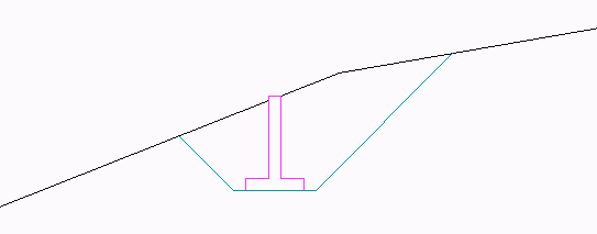
This command draws a retaining wall symbol in profile view and
draws the excavation tie slopes from the base of the wall to the
ground profile.
The program first prompts to select the retaining wall section
symbol. To add custom symbols, create a wallXX.dwg in the Carlson
SUP folder where XX is the wall number. For example, create a
drawing wall3.dwg in the %appdata%\Carlson
Software\Carlson2014\r18.2_x64\sup folder. This dwg should have one
polyline drawn left to right to outline the wall section. The
polyline should be open along the bottom. The wall1.dwg and
wall2.dwg are examples of how to draw the wall section
polyline.
After selecting the wall section, the program prompts for the
tie slope and the base placement offset which is the offset from
the base of the retaining wall to the bottom of the tie slope. Next
there are prompts for the horizontal and vertical scales of the
profiles which set the vertical exaggeration for the drawing. Then
the program prompts for the insertion point for the base of the
wall. Finally there is a prompt for selecting a ground polyline on
the profile to intersect with the tie slopes.
Tie slope ratio <1.000>: press
Enter
Base placement offset <1.000>:
press Enter
Horizontal Scale <50>: press Enter
Vertical Scale <50>: press Enter
Pick insertion point: pick a point
Select ground polyline (ENTER for None): pick
polyline
Total Wall Area: 12.00, Above Ground: 0.22, Below Ground: 11.78
Do another retaining wall [<Yes>/No]? No
Pulldown Menu Location: Profiles > Profile
Utilities
Keyboard Command: rwallsym
Prerequisite: None