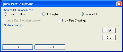
Quick Profile
This command allows you to create a profile in one step. The
alignment for the profile can be defined using picked points, a
centerline file or a polyline. The surface for the profile can be
defined by 3D screen entities, 3D polyline or surface files (grid
or triangulation).
Screen Entities: The
program creates the profile by finding the intersections of the
centerline with 3D linework entities in the drawing. There's an
option for whether to ignore entities at zero elevation.
3D Polyline: Creates a
profile using a selected 3D polyline. The polyline vertex
elevations are used for the profile elevations and the profile
stations are from the lengths of the polyline segments.
Surface File: This option
allows you to use one or two grid or triangulation surfaces.
There's also an option to Show Pipe Crossings which will find and
display pipe crossings from sewer networks and 3D polylines tagged
as pipes. The sewer network can be created in the Hydrology module.
To tag a 3D polyline as a pipe, use the Assign Pipe Data To
Polyline command.
Since picked points are the default for the horizontal alignment,
the command is as quick as select surface type (screen or file),
then Pick, Pick, Enter and view. The resulting profile is
displayed in a graphic dialog box with real time data reporting. As
the crosshairs are moved across the profile in the window, the
station, elevation and slope data corresponding to the current
crosshair location appear in the lower right of the window. A
second crosshair on the plan view corresponds to crosshair movement
along the profile so the user knows exactly where the current
profile point is on the plan view. Also the Adjust Alignment
function allows you to drag a horizontal alignment point and update
the profile in real-time.
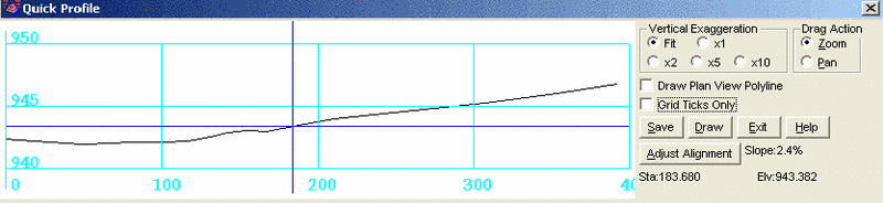
Vertical Exaggeration: Determines the amount of vertical
exaggeration for the profile in the window.
Drag Action: Determines whether the right mouse button
functions as "Zoom" or "Pan" in the profile window.
Grid Ticks Only: Instead of the full graph as shown above,
Grid Ticks only plots only ticks along the horizontal and vertical
axis near the station and elevation text.
Adjust Alignment: Allows you to pick a horizontal alignment
point and while moving it, the profiles are updated in real-time.
You can also select a horizontal alignment segment and move the
whole alignment position. The Adjust Alignment function is only
available when surface files are used as the source of the surface
model.
Save: Writes the current profile data to a .PRO file.
Draw: This draws the profile with grid in the drawing. The
user has options for horizontal and vertical scales and the layer
of the profile. The Draw Profile command includes more options for
drawing the profile. In order to use this command, you must first
create a .PRO file using the Save command described above.
Print: This makes a graphic
report of the profile in either PDF or DWF format as selected under
Settings->Configure.
Exit: Exits this command.
Help: Opens on-line help.
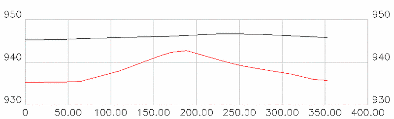
 Note that the Draw
option will exit the Quick Profile command after the drawing is
complete. A typical completed drawing, in this case with two
surfaces, is shown below. Note also that the horizontal stationing
text offset follows the setting in the Draw Profile command
itself.
Note that the Draw
option will exit the Quick Profile command after the drawing is
complete. A typical completed drawing, in this case with two
surfaces, is shown below. Note also that the horizontal stationing
text offset follows the setting in the Draw Profile command
itself.
Prompts
Pick starting point (CL-Centerline, P-Polyline):
screen pick alignment points for profile
Pick second point: pick next point
Pick next point (Enter to end): press enter to
end
Tested 58 of 58 Entities Intersects found> 33
Dialog Box
Pulldown Menu Location: Profiles
Keyboard Command: quickpro
Prerequisite: 3D screen entities or surface
file