Profile from Surface Entities creates a profile from contours, triangular mesh, and other 3D drawing entities. The method is to draw a polyline as the profile centerline. Then the profile is derived from the intersections of this polyline with the 3D entities. For added accuracy in pulling the profile, include the triangular mesh as well as the contours.
File: Displays the name of profile to be created.
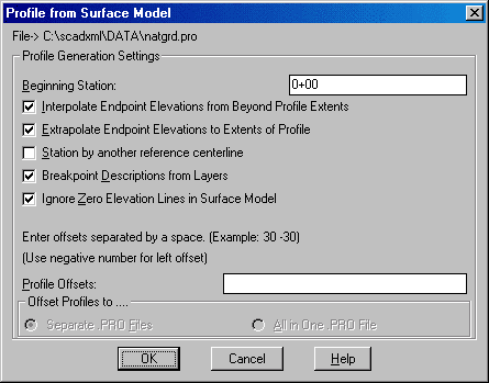
Beginning Station: Specify the beginning station for the
profile.
Interpolate Endpoint Elevations from Beyond Profile Extents:
When checked, the program will look past the ends of the centerline
for additional intersections with 3D entities. These additional
intersections will then be used to interpolate the elevation at the
starting and ending station of the centerline.
Extrapolate Endpoint Elevations to Extents of Profile: This
option uses the slope of the last two elevation points of the
profile and calculates the elevation of the endpoint from this
slope.
Station by another reference centerline: When checked, the
program will prompt you to pick another centerline polyline. The
intersection points along the first centerline are then projected
onto the second centerline. The profile then stores the elevation
of the intersection with the station along the second
centerline.
Breakpoint Descriptions from Layers: When checked,
breakpoint descriptions are assigned based on layer name of surface
entities. These descriptions are used in routines such as
Input-Edit Profile and Profile Report.
Ignore Zero Elevation Lines in Surface Model: When checked,
any zero elevations selected in the surface model are ignored.
Profile Offsets: Specify optional offset profiles. Enter
offsets separated by a space. Example: 30 -30 (to create 30' left
and 30' right offset profiles). After entering the offset values,
press TAB to select file options described below.
Offset Profiles to: Specify whether offsets profiles should
be created as separate profile (.PRO) files, or included in a
single profile (.PRO) file. Only available if you specify Profile
Offsets above. Offset profiles are automatically named by combining
the profile name and the offset. For example, if the profile is
named NATGRD.PRO and you create a 30' right offset profile, it will
be named NATGRD30.PRO.
Profile File to Write dialog Specify a new profile file
(.PRO) name to create.
Profile from Surface Model dialog Make choices, click
OK.
Polyline should be drawn in direction of increasing
stations.
CL File/<select polyline which represents the profile
centerline>: pick the centerline (Do not press
Enter.)
Select Lines, PLines, and/or 3DFaces that define the surface for
profiling.
Select objects: C (for crossing and window everything
the centerline crosses) or All (to select all objects on the
drawing)
Keyboard Command: prosm
Prerequisite: A polyline centerline and surface lines and
polylines.