This command creates a .PRO file using the X-Y distances between user-specified points for sequential stations and the Z values at these points for profile elevations. Unlike many of the Carlson profile routines, this routine does not require a pre-determined horizontal project alignment. Point numbers or screen picks (on entities with elevation) may be used to define the profile. If point numbers are used, a series of numbers may be abbreviated (1-20) or multiple non-sequential point numbers can be entered in one string provided they are separated by a comma.
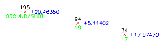
Pick point or point numbers (Enter to end): 34
Point number: 34 Desc: 17
(4088.82 4048.75 17.9747)
Pick point or point numbers (Enter to end): 94
Point number: 94 Desc: 18
Station: 1150.0727
(4898.41 4865.6 5.11402)
Pick point or point numbers (Enter to end): 195
Point number: 195 Desc: GROUND/SHOT
Station: 2253.0427
(4160.4 4045.91 20.4635)
Pick point or point numbers (Enter to end):
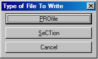
A dialog appears
which offers the option to store the data in a profile, in a
section file or cancel.
Type of File to Write
dialog Choose Profile
If you choose Section, you will make a section file with Station 900001, which can be plotted as a cross section. The section is left-justified, with the first point representing offset 0 and all other offsets to the right. The section offsets will match the profile stationing if the same points are used.
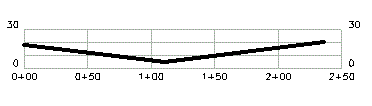
Opened file: c:\scad2005\data\drawing431.pro
Profile Data stored in: c:\scad2006\DATA\Drawing431.PRO
In this graphic showing the points 34, 94 and 195, note
that the "+" in front of elevations higher than 0 is an option
within Draw-Locate Points.
Pulldown Menu Location: Profiles > Profiles from
...
Keyboard Command: pro3dpt
Prerequisite: Plot points or contour lines with real Z axis
elevations.