
This command creates design slopes from a perimeter polyline at
specified cut/fill slopes to reach existing ground. This routine
can be used to design building pads, pits, roads, ditches,
stockpiles, etc. The design is drawn as 3D polylines for the
cut/fill slopes and for the daylight perimeter where the design
meets existing ground.
Before beginning this routine, you must have drawn the polyline
representing the outside edge of the feature to model. The edge is
drawn as a polyline which can be either a 2D or 3D closed or open
polyline. For a 2D polyline, the program will prompt for an
elevation for the pad perimeter. With a 3D polyline, the pad
perimeter is set to the elevations of the 3D polyline. For an open
polyline, the program will prompt for the side for the design. With
a closed polyline, the program designs the slopes either outward or
inward depending on the settings in the dialog.
Under Source of Slope Target Surface Model, choose between a Surface File (.GRD, .FLT, .TIN), Screen Entities, or a specific Elevation. If using Screen Entities, the routine internally calculates a gridded model, the limits of which are specified by screen picks. Make sure that the grid area covers the entire area for the pad including room for the cut/fill slopes.
For closed pad perimeters, there is a Slope Direction from
Closed Plines option to draw the slopes inward or outward from
the perimeter. The outward method starts the slopes at the design
elevation of the perimeter and projects out to intersect the
existing surface. The inward method projects the slopes inside to
reach the grid surface or a set elevation. Outward sloping would be
used for such things as building pads, parking lots, etc. where the
interior remains as a defined surface. Inward sloping would be used
for such things as the top edge of an excavated pit or pond where
the interior side slopes project downward at the specified slopes
until reaching the original ground surface.
The Slope Projection
Perpendicular To option applies to sloping pad perimeters.
The Pad Polyline method creates the user-specified slope
perpendicular to the pad perimeter. The Slope Direction method
accounts for the slope of the pad perimeter and makes the final
surface to match the user-specified slope. For example, if the pad
perimeter is at a 10% slope and the fill slope is at 2:1, then the
Pad Polyline method would create fill slopes that are 2:1
perpendicular to the pad while slightly steeper (1.96:1) for the
actual slope that goes in the slope direction with the effect of
the sloping pad perimeter. For the same case except with the Slope
Direction method, the resulting slope perpendicular to the pad is
less steep (2.04:1) while the actual slope in the slope direction
is exactly 2:1.
Under Design Slope Format, choose between Ratio, Percent, Degree or Template. The use of a Template allows
for complex slopes to be applied, and is also an alternative
approach to road design. The template (.TPL) file is created in the
Design Template routine in the Roads menu. When using a
template, the pad perimeter represents the centerline. One way to
create the pad perimeter for the template is to use the Profile
to 3D Polyline command which converts a 2D centerline to a 3D
polyline using a design profile. With a template, the program uses
not only the cut and fill slopes from the template file but also
draws all the template grade points such as edge of road, curb and
ditch. The subgrade, superelevation and template transition options
of the template file are not used in this command. These options
are only applied in the Process Road Design command. The
grade points are drawn as 3D polylines parallel with the
centerline. Cross section 3D polylines that include the grade
points are also drawn at the specified interval.
The Force Cut option
will try the cut slope to find a catch point even when the pad
perimeter starts out in fill. This is possible when the existing
ground is rising faster than the cut slope. Likewise the
Force Fill option will try
the fill slope to find a catch point when the pad starts out in
cut.
The Process Multiple Pad
Polylines option allows you to process multiple pad
perimeter polylines at a time instead of a single pad perimeter.
The program will prompt for a selection set of pad perimeter
polylines and then cycle through and run the design on each one.
There will be one final report for the earthworks for all the pads.
The Setup function allows you to specify different cut/fill slopes
by layer and also to set the processing order by layer. For
example, in the case of processing both building pads with a
shallow slope and ditch polylines at a steeper slope, you could set
up the processing order to do the building pad first and the ditch
last so that the ditch cut slopes will carve out any overlap with
the building fill slopes. These pad layer slope and order
assignments can be saved and loaded from a .PAD file.

Use Another Surface for Pad Interior will bring up a prompt for another Surface file (.GRD, .FLT, .TIN) to use for the design surface within the starting pad perimeter. Otherwise the program will model the pad interior by straight interpolation from the starting pad perimeter elevations. For example, if a building pad has a starting pad perimeter at a set elevation and the pad is supposed to be flat, then this option is not needed. This option is needed in a case where you are designing a pit and the starting pad perimeter is a 3D polyline that follows an undulating pit bottom surface. The pad design will model the pit side slopes. In order to model the undulating bottom of the pit, you need the Use Another Surface for Pad Interior option to select a surface that models the pit bottom.
Use Different Slopes for Separate Sides allows you to
specify different slopes for different sides of your pad polyline.
If this is toggled ON, the Assign Pad Cut/Fill Slopes dialog is
invoked, where you can create multiple Slope Groups along the Pad
Template polyline and set the Cut and Fill design ratios for
each.

Use Slope Pad Design allows you to set a cross slope amount for the top of the pad. You will be prompted to screen pick two points that designate the slope direction. For automatic balancing of cut/fill quantities, you will be prompted to find the optimal slope and slope direction.
Draw Slope Direction Arrows draws an arrow on the outslopes that points in the downhill direction. Arrows on fill slopes are drawn as solid filled.
Solid Cut Arrows allows you to choose between drawing the cut arrows as solid filled or as wire frame.
Round Exterior Corners holds the outslopes around the
corners. Otherwise the side outslopes stay straight until they meet
at the corners as shown in the figure.
Erase Previous Pad
Entities erases drawing geometry created with this command
previously.
When Draw Side Slope Polylines is ON, Design Pad Template
will draw 3D polylines perpendicular to the pad perimeter from the
pad to the catch point.
Color Side Polylines
assigns different colors to Cut and Fill Side Polylines to make
them easier to distinguish.

|
| Example of pit design for option of Use Another Grid for Pad Interior |

|
| Pad corner without round corners option |
|
| Pad corner with round corners option |
Side Polyline Spacing specifies the interval at which to
draw the Side Slope Polylines. Besides at the interval, side slope
polylines are also drawn at grid corners.
Corner Delta Angle is
the delta angle in degrees between side slope polylines to span the
delta angle around exterior corners.
Cut volume is multiplied by the Cut Swell Factor in the final volume report.
Fill volume is multiplied by the Fill Shrink Factor in
the final volume report.
The Contour Pad option
draws contours on the pad. At the end routine, a dialog lets you
set the contouring options. Usually you should specify a new
contour layer and turn off smoothing.
The Write Final Surface
option creates a surface model of the pad using the elevations of
the pad within the disturbed area polyline and using the original
ground surface everywhere else. At the end of the routine, the
program will prompt for the surface file name to create.
The Trim Existing Contours Inside Pad option trims existing contours inside the disturbed limits of the pad.
You must specify the Pad Layer Name that the pad 3D polylines will be drawn on.
There is an option to calculate volumes for the pad design. The volumes are calculated by comparing the existing surface with the pad design. The inclusion perimeter for the volume calculation is the daylight perimeter polyline which represents the limits of disturbed area. The existing surface model is defined by the existing surface file (.GRD, .FLT, .TIN) or screen entities selected at the beginning of the command. The pad design surface is calculated by making a surface from the pad 3D polylines including the starting pad perimeter, the side polylines and the daylight perimeter.
Besides calculating the volumes in the Design Pad Template routine, you can
also calculate the volumes with the Two Surface Volumes command, or the
Volumes by Triangulation
command. Two Surface Volumes works with two grid files, Volumes by
Triangulation works with two TIN files. The design surface for Two
Surface Volumes can be the final output surface from Design Pad or
you can create a design surface with Make 3D Grid File using the 3D
polylines created in Design
Pad. You could also create a TIN surface of the design
surface using Triangulate and
Contour. Some of the reasons to use either the Two Surface
Volumes command or the Volumes by Triangulation command are that
these volume routines have more output options (cut/fill color
maps, etc.) and you can check the volumes by plotting or contouring
the surface files. Also, you can combine several pads and
other final surfaces by running Make 3D Grid File or Triangulate and Contour and then use
these volume commands to calculate the overall site
volumes.
The design is drawn as 3D polylines and the earthwork volumes
are calculated. Before ending, the program allows you to adjust the
design by changing the pad elevation, slopes and offset. The
program can find the cut/fill balance by automatically adjusting
the pad elevation. If adjustments are specified, the pad polylines
are redrawn and the volumes recalculated.
A few Key things to
note:
First you are presented with the Design Pad Template dialog
box.
If the Source of Slope Target Surface Model is set to a Surface
File, you will first be asked to:
Pick the top of pad polyline: select perimeter
polyline
Then the Select Slope Target Surface dialog box is
presented. Choose the Slope Target Surface file, pick
Open. You then proceed to enter the slope parameters of the
pad...
If the Source of Slope Target Surface Model is set to a Screen Entities, you will first be asked to:
Pick Lower Left limit of pad disturbed area: pick
lower left These prompts appear for the Screen Entities surface
model method.
Pick Upper Right limit of pad disturbed area: pick upper
right Be sure to pick these limits well beyond the area of the
top of pad polyline in order to make room for the outslopes.
Make Grid File Dialog After selecting the limits of the
disturbed area the program will generate a 3D grid that represents
the surface. Specify the grid resolution desired and select
OK.
Then,
Pick the top of pad polyline: select perimeter
polyline
Then proceed to enter the slope parameters of the
pad...
Enter the fill outslope ratio <2.0>: 2.5
Enter the cut outslope ratio <2.0>: 2.5 After
entering outslopes slope ratios, a range of elevations along the
pad top will be noted.
Enter the pad elevation <29.54>: 39
Calculate earthwork volumes (<Yes>/No)? press
Enter
Report Viewer Reports cut/fill volume.
Adjust parameters and redesign pond (Yes/<No>)?
press Enter
Write final surface to grid file
(Yes/<No>)? press Enter
Trim existing contours inside pad perimeter
(Yes/<No>)? press Enter
Contour the pad (<Yes>/No)? press
Enter

|
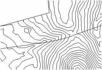
| Existing contours with top of pad perimeter polyline |

|
| Pad template with contours |
|
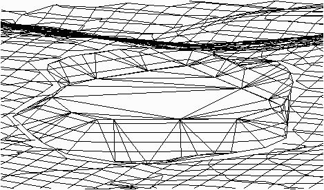
| 3D view of pad with DTM of surface and triangulation faces of pad |

|
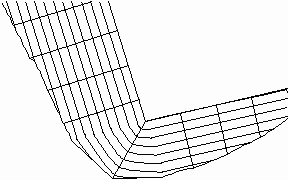
| Template to apply in Design Pad Template |
|
| Existing surface with 3D polyline centerline |

|
| Result of Design Pad Template
showing template grade polylines, cross section polylines, cut/fill slopes, and final contours |

|
| Viewpoint 3D view of Design Pad Template |
|
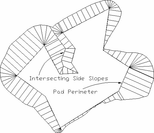
| Design Pad Template can also handle self-intersecting side slopes |
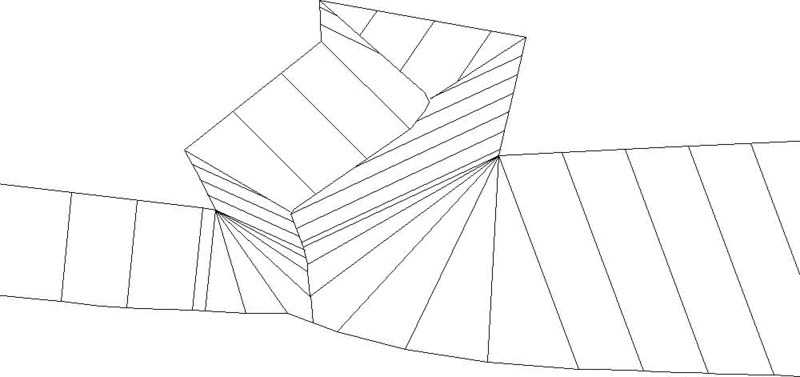
|
| Viewpoint 3D view of intersecting side slopes |
Pulldown Menu Location: Surface
Keyboard Command: pad
Prerequisite: A pad perimeter polyline and surface entities
or a surface file for an intercept target.