 Distance for Stations is the primary interval
for stationing. On Curve
allows for a different interval for curve segments verses line
segments.
Distance for Stations is the primary interval
for stationing. On Curve
allows for a different interval for curve segments verses line
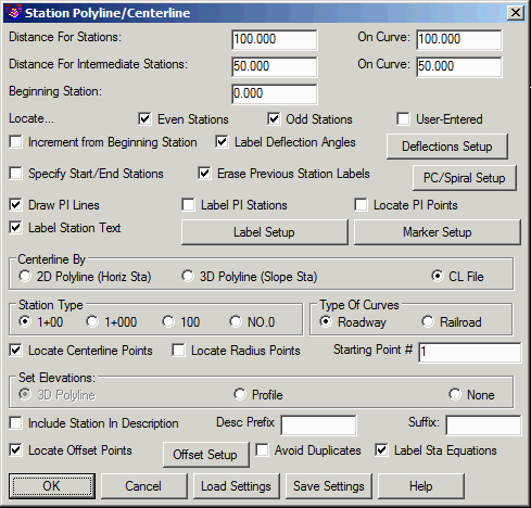
segments.This command will station a polyline or centerline file at a
given interval distance. The options for this command are set in
the dialog shown below. After setting the options, click OK on the
dialog and then pick the polyline or select the centerline
file. All settings can be saved as (.STA) files and loaded
for reuse, and for storing multiple stationing schemes.
Polyline/Centerline station labels are also dynamic, and so will
update when changes are made in the geometry.
Distance for Stations is the primary interval
for stationing. On Curve
allows for a different interval for curve segments verses line
segments.Distance for Intermediate Stations is the intermediate
interval for stationing. On
Curve allows for a different interval for curve segments
verses line segments.
Beginning Station is the beginning station of the centerline for stationing.
Locate Even Stations labels the stations at the distance interval (i.e. 2+00, 3+00, etc.).
Locate Odd Stations labels the non-interval stations at the polyline/centerline end points and PC and PT points.
Locate User-Entered prompts you for individual stations to label.
Without the Increment Station Labels from Beginning
Station option, the program increments the station labels from
zero. For example, if the station interval is 100 and the polyline
starting station is 145, then the program will label 2+00, 3+00,
etc. With this option active, the station labels are incremented
from the starting station. In this example, the program would then
label 2+45, 3+45, etc.
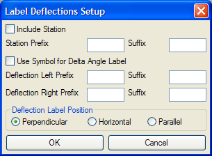
Label Deflection Angles
adds this annotation to the stationing. Settings for this are
specified in the Label Deflections
Setup, accessed by the Deflections Setup button.
 When Specify Start/End
Stations is checked, only the stations between and including
the specified starting and ending stations will be labeled. If
locate centerline points and offset points are toggled on, only
points within the specified stations will be located.
When Specify Start/End
Stations is checked, only the stations between and including
the specified starting and ending stations will be labeled. If
locate centerline points and offset points are toggled on, only
points within the specified stations will be located.
When Erase Previous Station Labels is checked,
previous station labels are erased when new ones are
generated.
The PC/Spiral Setup PC button accesses the PC/Spiral Setup dialog, where settings
are controlled for lines and/or symbols and/or labels at the
starting and ending (PC and PT) stations of an arc of the
centerline as well as for the spiral special stations (TS, SC, CS,
ST).
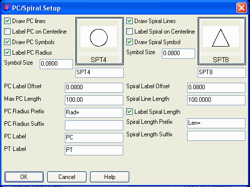
When Label PC On Centerline is checked, the station of the PC and PT will be labeled on the centerline as well as the PC and PT lines. When not checked only the PC and PT lines will be labeled.
Draw PC Symbols
controls whether symbols are placed at these locations. If
checked, the desired symbol is selected by picking on the box to
the right.
Label PC Radius controls whether this point is labeled.
Max Length controls the maximum length for the PC lines
to be drawn described above.
Back in the main Station
Polyline/Centerline dialog box:
Draw PI Lines draws a 2
segment polyline in both tangent directions from the PI as a marker
for the PI.
When Label PI Stations is
checked, the PI station is labeled at the PI point.
When Locate PI Points is
checked a point will be created at the PI of a horizontal curve
graphically and written to the active coordinate file.
When Label Station Text is checked, this command places
station text along the polyline at the angle of the corresponding
segment. After toggling this option on, the Label Setup button will become
available for selection. Select it to configure the label settings
as desired. Select the Marker
Setup options to modify the size of the markers for certain
types of stations. See definitions following the dialog
box.
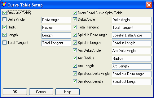
 Also under PC/Spiral Setup is Curve Table Setup which controls
whether to draw data tables for the curves and spirals. When this
option is on, the program creates a data table with the selected
fields for each curve and automatically places each table to the
outside of the curve.
Also under PC/Spiral Setup is Curve Table Setup which controls
whether to draw data tables for the curves and spirals. When this
option is on, the program creates a data table with the selected
fields for each curve and automatically places each table to the
outside of the curve.
 Label Setup
The Marker Setup options control the size of markers for
different station types as well as the layer the markers will be
drawn on. The Half Size Main options draw a perpendicular tick mark
on only one side of the centerline. Otherwise a full marker is
drawn that goes on both sides of the centerline. There are separate
Half Size options for the main station interval, intermediate
station interval and odd stations.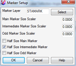 Specify
whether to define the Centerline By picking a 2D polyline or
3D polyline in the drawing or selecting a centerline (.CL)
file.
Specify
whether to define the Centerline By picking a 2D polyline or
3D polyline in the drawing or selecting a centerline (.CL)
file.
Use Station Type to specify the stationing format to
use.
Use Type of Curves to specify whether you are labeling a roadway curve (arc definition) or railroad curve (chord definition).
Locate Centerline Points will locate points and store
them in the current CooRDinate file.
Locate Radius Points will locate the radius points of any
arc segments.
Starting Point Number determines the starting point
number for the points to be located.
Vertical Exaggeration applies to Profile Polyline mode.
This factor is the ratio between the horizontal and vertical scales
on the profile grid.
There are two ways to Set Elevations for the centerline
points and offset points to be created.
When Include Station in
Description is checked, the station along the centerline
will be included in the resulting offset point.
Description Prefix is an
optional user-specified prefix to be added to the point
description.
Description Suffix is an optional user-specified suffix to be added to the point description.
When Label Sta Equations is checked on any station equation, contained in a centerline (*.cl) file will be labeled. This option is only available when stationing a centerline file (*.cl).
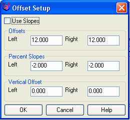
Locate Offset Points will create points at the specified
left and right offset distances from the centerline. Options for
setting the elevations and descriptions of the points are available
from the Offset Setup dialog.
Station Polyline Dialog
Polyline should have been drawn in direction of increasing
stations.
Select polyline that represents centerline: select a
polyline
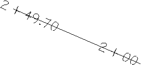
|
| Closeup of Station + at Tick Mark option |
|
| Labels with Label PC on Centerline checked on |

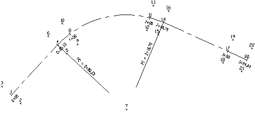
|
| Labels set to perpendicular and Max Length of PC lines set to 75.0 |

|
| Labels with Draw PI Lines, Label PI Stations and Locate PI Points all checked on |
|
|
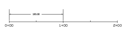
Labels using Centerline By 2D Polyline (Horizontal Station) |
|
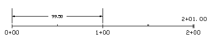
| Labels using Centerline By 3D Polyline (Slope Station) |
Pulldown Menu Location: Centerline
Keyboard Command: stapl
Prerequisite: A polyline
or CL file