 The Store Points to Coordinate
File option will store any points the current coordinate (.CRD)
file. This includes centerline points and offset points.
The Store Points to Coordinate
File option will store any points the current coordinate (.CRD)
file. This includes centerline points and offset points.This command creates points along a centerline at specified
stations and left and right offsets. The centerline can be defined
by a polyline, centerline (.CL) file or two points.
The Store Points to Coordinate
File option will store any points the current coordinate (.CRD)
file. This includes centerline points and offset points.
When Locate Points on Centerline is checked, the program will locate points along the centerline, otherwise just the offset points will be created.
When Label Stations & Offsets is checked, the program
will label the station-offset as the point description
attribute.
The Include Station-Offset In
Description option will add the station and offset of the
point into the point description.
Beginning Station:
Enter the Beginning Station of the Centerline.
Use Centerline from to specify whether to define the centerline by picking a polyline in the drawing, selecting a centerline (.CL) file, or using 2 points.
Use Reference Elevation to assign elevations to the points created when locating points on the centerline of offset points. When using a 3D Polyline for the elevation reference, points will be created at the station entered and the offsets specified with the elevation of the same station along the 3D polyline. The Profile option will do the same as the 3D Polyline option only it will use a profile file for the elevation reference. You will be prompted for the profile to use for the elevation reference. None simply creates 2d point data on elevation zero. The Reference Elevation option is good for creating points along the centerline for final grade elevation points. Profile to 3D polyline can be used to transfer the profile data to the polyline before calculating the final grade points.
Cross Slope %: This
option is used to alter the elevations of the new points by
applying either a Cross Slope calculation or a Delta Z
variable.
The Manual Entry option in Input Station-Offset from will
prompt for the station and offset distances. The Read File option will read the stations
and offsets from a text file. The text file format with point
number, station, offset, elevation and description. The program
handles station formats with or without the '+' (i.e. either 250 or
2+50). The elevation and description are optional. The Read File
option is a quick routine to convert a station-offset data file
into coordinates. The delimiter for the text file and the order of
the fields are set in the dialog shown here.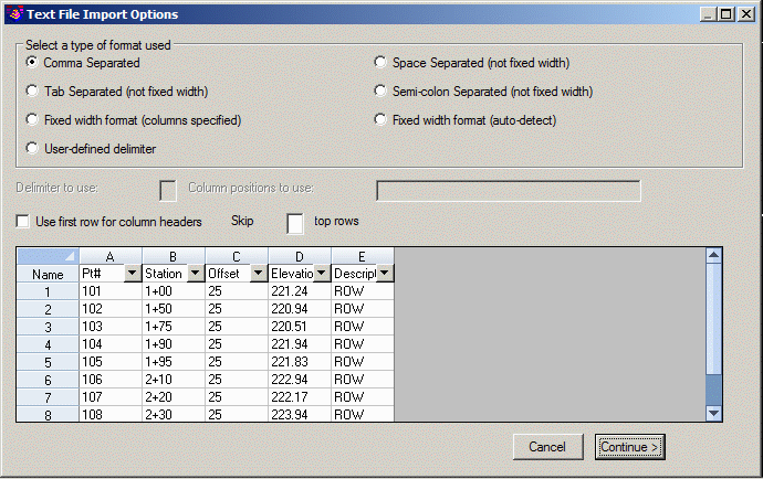 When Offset Prompt is set to Both Left-Right,
the program will prompt for left and right offsets. If you respond
to an offset prompt with zero (0), no offset point is created. The
Single Offset option will prompt for one offset per station. Enter
a right offset with a positive value and a left offset as a
negative value.
When Offset Prompt is set to Both Left-Right,
the program will prompt for left and right offsets. If you respond
to an offset prompt with zero (0), no offset point is created. The
Single Offset option will prompt for one offset per station. Enter
a right offset with a positive value and a left offset as a
negative value.
Use Station Type to specify the stationing format to use.
Use Type of Curve to specify whether the curves are for a roadway or railroad.
Offset Point Settings Dialog
Polyline should have been drawn in direction of increasing
stations.
Select Polyline near endpoint which defines first station.
[nea on] Select Polyline to Station-Measure: select a
polyline
(5309.0 4845.0) Station: 0.00
(5526.0 4917.0) Station: 228.63
Distance from beginning station along centerline (Enter to
end): 110
Starting Segment Station: 0.0 Ending Segment Station: 228.633
Working Line segment...(5413.4 4879.64 0.0)
Left offset distance <10.0>: 15
Right offset distance <15.0>: 20
Distance from beginning station along centerline (Enter to
end): press Enter
Keyboard Command: offpts
Prerequisite: A centerline (.CL) file, polyline, or two
points