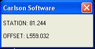
This command calculates the station and offsets of point
coordinates relative to a centerline. The points to calculate can
be stored in a coordinate (.CRD) file or picked on the screen. As
the crosshairs are moved, the station and offset of the current
position are displayed in real-time in a small window (see
example).
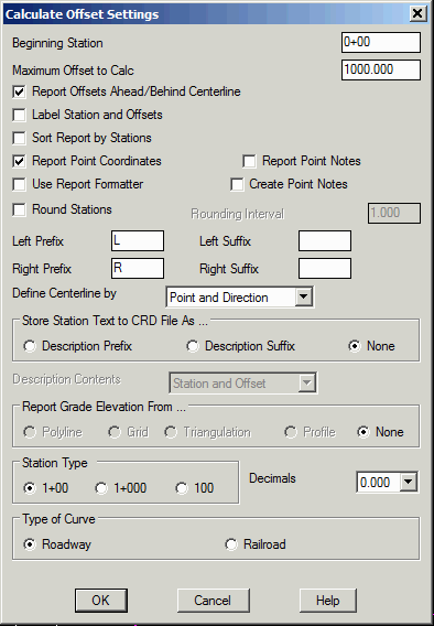
Beginning Station: Specify the beginning station of the
centerline. The polyline should be drawn in the order of increasing
stations. Not available when you use a centerline (.CL) file to
define the centerline.
Maximum Offset to
Calc: This is the maximum distance from the Centerline
for which offsets are calculated.
Report Offsets Ahead/Behind Centerline: When checked, this option shows offsets for points or picked points located before the beginning station and after the ending station of the centerline.
Label Station and Offsets: When checked, the station
offsets will be labeled in the drawing.
Sort Report by Stations:
When checked, this option will report the station-offsets in
station order no matter what order the points were calculated.
Report Point Coordinates: When checked, this option will
include the point northing and easting in the report.
Report Point Notes: When
checked point notes will be included on the calculate offset
report.
Create Point Notes: When
checked, the station and offset of the offset point will be created
as notes and written to a note file (*.not). This note file will
have the same name as the crd file.
Use Report Formatter: When checked, the output of this command is directed to the Report Formatter which allows you to customize the layout of the report fields and can be used to output the data to Microsoft® Excel or Microsoft® Access. You must check this option on in order to use the Report Grade Elevation From option.
Round Stations: When checked, this option will round the
stations for the selected points on the report to the Rounding
Interval specified. For example if an offset point is located at
station 1+01, and the rounding interval is set to 10, then the
report will show the offset point at station 1+00.
Left/Right Prefix/Suffix: These settings are used with
the offset label.
Store Station Text to CRD File: When checked, the station offset text is appended to point numbers that are selected.
Report Grade Elevation From: When checked, this option will calculate an elevation for each point from a 3D polyline, grid file (.grd) or triangulation (.flt) file. To Use this option, the Report Formatter must be toggled on. The grade elevation is reported and compared with the point elevation to report the cut/fill. For the 3D polyline option, the grade elevation is calculated by finding the elevation at the point on the 3D polyline that is the nearest perpendicular position from the offset point. The 3D polyline that is used for elevations does not need to be the same polyline that is used as the centerline for the station-offset calculations.
Define Centerline by: Specify whether to define the
centerline by picking a polyline in the drawing, selecting a
centerline (.CL) file, by a point and direction angle, or using 2
points. The polyline mode can be either 2D or 3D for horizontal or
slope distance stationing.
Station Type: Specify the stationing format to use.
Decimals: Specify the display precision for the stations and offsets.
Type of Curve: Specify whether the curves are for a roadway or railroad.
Calculate Offset Settings Dialog
Polyline should have been drawn in direction of increasing
stations.
Select Polyline near endpoint which defines first station.
[nea on] Select Polyline Centerline: select polyline
centerline
(5309.0 4845.0) Station: 0.00
(5526.0 4917.0) Station: 228.63
PtNo. North(y) East(x) Elev(z) Description
140 4889.13 5410.25 0.00 1+10.00L10.00
Station on Line> 1+10.00 Offset> 10.00 Left
PtNo. North(y) East(x) Elev(z) Description
141 4870.15 5416.55 0.00 1+10.00R10.00
Station on Line> 1+10.00 Offset> 10.00 Right
+ before station denotes point is ahead of line segment, - denotes
beyond.
Pick point or point numbers (Enter to End): 22-28
 Station  Offset  Description  Elev  Pt#  North    East

4+95.89L  15.48   Catch Basin  0.00  22   4811.00  4454.00

5+78.43L  58.18   Power Pole   0.00  23   4839.00  4548.00

6+77.26L  57.28   Power Pole   0.00  24   4868.00  4656.00

9+01.55R  16.81   Catch Basin  0.00  25   4745.00  4887.00

10+50.51L 25.39   Traffic Sign 0.00  27   4872.00  5043.00

4+03.48R 22.15    Light Pole   0.00  28   4657.00  4454.00
Pick point or point numbers (Enter to End): press Enter
Keyboard Command: calcoff
Prerequisite: A centerline (.CL) file, polyline or two
points