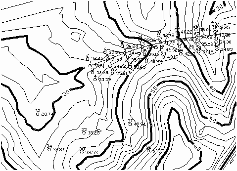
This command will calculate the Z coordinate of any point that falls within the surface model. Use this command to calculate the elevations for points of a design for slope staking or for putting spot elevations on a topography map. The calculated points can be stored in the current coordinate (.CRD) file. A surface model is either selected from a grid (.GRD) or triangulation (.TIN or FLT) file or internally calculated from the existing entities on the drawing.
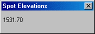
Spot elevations can be calculated at various user-specified points or at a specific interval. For random spot elevations, the user picks or enters the X,Y coordinates for each spot elevations. The elevation at the current position of the crosshairs is displayed in real-time in a small window. For interval spot elevations, the alignment for the intervals is defined by a polyline that must be created before starting this routine.
Source of surface model (File/<Screen>)? press
Enter Use the File option to select a grid (.GRD) or a
triangulation (.TIN or .FLT) file.
Layer for points <POINTS>: press
Enter
Add spot points to Coordinate File (Yes/<No>)?
Yes This option stores any points created in this routine to
a .crd file and draws Carlson point entities.
Draw nodes only (Yes/<No>)? press Enter
This prompt only appears if Add points to Coordinate File is off.
This option either draws only POINT entities or an X mark and
elevation text.
If you specified the use of a file for the surface model, you are then prompted to select the surface model file.
If you specified the use of Screen entities, you are prompted
for:
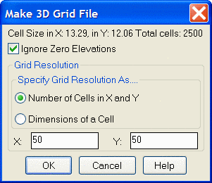
Pick Lower Left limit of Surface area:
Pick Upper Right limit of surface area:
then the following
dialog box appears with the settings to make a 3D Grid file:
For picked point spot elevations:
Random spot elevations or interval along pline
(<Random>/Interval)? press Enter
Enter or pick point (Enter to end): pick a point
Enter or pick point (Enter to end): press
Enter
For spot elevations along a polyline:
Random spot elevations or interval along pline
(<Random>/Interval)? Interval
Pick the centerline polyline: pick a polyline
Interval along polyline <50.0>: 25
Number of left offsets <0>: 1
Enter left offset interval <25.0>: 10
Number of right offsets <0>: 2
Enter right offset interval <10.0>: press
Enter
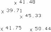
|
|
| Spot
Elevations with Add to Coordinate File off and Draw Nodes Only off |
|
|
Interval spot elevations for points 1-32 "Random" spot elevations for points 33-37 |
Pulldown Menu Location: 3D Data
Keyboard Command: spotelv
Prerequisite: Surface entities or a grid (.GRD) file