This command establishes grade rules for use in elevating lot
edges with respect to a reference 3D polyline such as a road edge
or other feature that must remain at its established elevations.
Elevating lot edges will create 3D linework along selected lot
edges in the drawing and set them at their designated elevations
based on the rules established by this command (see Elevate Lot Edges By Grade Rules for a
more detailed explanation).
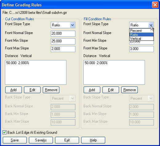
This routine defines the actions to take when elevating lot
edges by grade rules, establishing three categories of slopes to
create (normal, minimum, and maximum) in the two possible
conditions that will occur (cut or fill), for the two edges of the
lots being elevated (front edges and back edges). You may also
establish intermediate grade breaks along the side lot lines by
adding or editing additional grading rules in the middle windows.
You define both cut and fill conditions in this routine, and the
Elevate Lot Edges By Grade
Rules command will use the appropriate condition based on
whether the lot edge is in cut or fill at any given location with
respect to a selected reference grade line such as a road edge or
other feature.
Options:
Slope Type: Choose which type of slope to define, either
percent, ratio, or
vertical difference.
Normal slope: Set the
desired slope to use in initial lot line elevation. This is the
slope that is applied whenever you first execute Elevate Lot Lines By Grade Rules. Note
that positive slope values are from the reference grade line
up to the front lot line,
negative slope values are from the reference grade line
down, and may be set either
positive or negative for either cut or fill conditions. This is
useful to force positive drainage toward a roadway, even where the
reference grade line is in a fill condition.
Min/Max Slope: These slope
values are the limits for automatic adjustment in balancing the
final grading of the lots in the RoadNET routines. The lot lines'
slopes are adjusted to values between these two limits to achieve
balanced cut and fill, and if balance is not achieved within these
limits, then the entire site is raised or lowered to reach a
balanced condition.
Side Line Grade Breaks: The
middle windows in the dialog allow you to add, edit, or remove
additional grade breaks along the side lot lines and are
established at a distance from the previous grade break (either the
front line or the previously defined break point), at a given slope
(again, defined using percent, ration, or vertical difference).
Back Slopes: These values
are for establishing the back lot lines' slopes from the last
encountered grade break (either the front line, or intermediate
grade breaks).
Back Lot Edge At Existing
Ground: Selecting this option will make the back line slopes
portion unavailable, and establish their elevations at the existing
grade in their location. This will also prompt for selection of the
existing surface model when executing the Elevate Lot Lines By Grade Rules
routine to establish the required elevations along the back lot
lines. Besides locating the back lot corners at the existing
ground, this option will also drape the back lot edge on existing
ground and add vertices into the back lot edge as needed to follow
any undulations in the existing ground surface.
Pulldown Menu Location: 3D Data >> Elevate By Grade
Rules
Keyboard Command: roadnet_grr
Prerequisite: None.