This command breaks 3D polylines against a surface. The surface is defined by a 3D grid or triangulated surface model which can be selected from a .grd, .flt or .tin file. Alternately, the user can select 3D entities on the screen from which the program internally calculates a 3D grid. This routine is one step in 3D polyline design. In this example, a valley fill is designed using 3D polylines as follows:
Source of surface model (File/<Screen>)? press
Enter The File option
allows you to choose the .grd, .flt, or .tin file that models the
site. Otherwise, a grid will be calculated by picking the grid
location and selecting surface entities on screen (e.g., contour
polylines). Using the File
option can be quicker because the surface is already calculated.
Also the .grd file can be drawn to preview the existing
surface.
Pick Lower Left limit of surface area: pick a
point
Pick Upper Right limit of surface area: pick a
point
Make GRiD Setting Dialog OK
Select polylines to clip.
Select objects: pick the 3D polylines
Select surface entities.
Select objects: select objects that define the
surface.
Erase polyline below surface (<Yes>/No)? press
Enter If you answer yes, the segments of the polylines below
the surface will be erased from the intersection, if any, of the
polyline with the surface. Otherwise the polylines will only be
broken into separate polylines at the intersection.
Specify layer names (Yes/<No>)? press Enter If
you answer yes, you will have the option to place the broken
polylines into different layers.
|
|
|
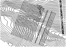
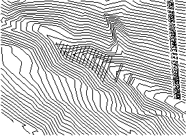
| Before Break 3D Polyline by Surface | After Break 3D Polyline by Surface |
|
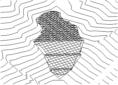
| 3D view of fill with grid mesh |
Pulldown Menu Location: 3D Data
Keyboard Command: surfbreak
Prerequisite: Plot the 3D Polylines to use for selection and
entities that define a surface.