.gif)
.gif)


Target points always exist as a sub-item of a Scan Position and are in that scan position's local coordinate system. This means that a project can have several sets of target points (one for each scan position). There are two ways to manipulate Target Points:
| Edit | Launches the Target Points Editor |
| Delete All | Deletes all Target Points. The user is prompted via a dialog box to confirm the deletion. |
| Import | Launches the ASCII file import dialog box. |
| Export | Launches the ASCII file export dialog box. |
| Transform | Launches the Transform dialog box to allow the user to define a transformation sequence to apply to the target points. |
| View | Launches the Scene creation dialog box to create a scene for viewing the target points. |
| Draw | Draws the Target Points in CAD. The user is prompted via a dialog box for the layer to draw the Target Points on. |
Several commands are available in both the Right-Click menu and in the Target Points editor. The difference between a command in the Right-Click menu and in the Target Points editor is the Right-Click menu commands operate on all target points. The Target Points editor commands operate on only the selected Target Points. If no target points are selected the users is asked if they wish to perform the operation on all target points.
The Target Point Editor is activated when the user right-clicks Target Points and selects Edit. In the Target Point editor there are several base functions that are shared across all point types.
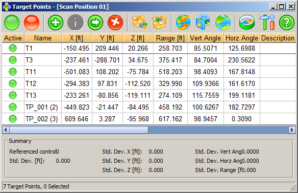
The title bar will display the scan position that the target points are part of. Just below that is a toolbar with several icons. The icons and their corresponding functions are as follows:
|
|
Activate Target Point toggles the selected target point(s) to be active in the current project. |
|
|
Deactivate Target Point toggles the selected target point(s) to be inactive in the current project. |
|
|
Add target Point brings up a dialog that allows you to specify the properties of a new target point to add. |
|
|
Edit Target Point brings up the target point edit dialog which allows you to change properties of the currently selected target point. |
|
|
Copy Target Points allows you to copy the currently selected points to another point set (such as from the target points to the control points of a scan). |
|
|
Delete Target Points deletes the currently selected target points. |
| Import Target Points brings up the ASCII file import dialog. | |
|
|
Export Target Points brings up the ASCII file export dialog. |
|
|
Transform Target Points allows you to define a transformation sequence to apply to the target points. |
|
|
View Target Points brings up the scene creation dialog for viewing the current target point set. |
|
|
Register Scan Position begins the scan registration process for the current set of target points. |
|
|
Coordinate System allows you to choose the coordinate system the positions values are in (Global or any current scan positions) |
|
|
Settings allow you to configure what properties of the points are visible in the spreadsheet control. |
|
|
Help brings up help documentation. |
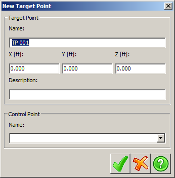
Name will specify a unique name to be used for
the Target Point in the project.
X, Y and Z may
be in feet (ft) or Meters (m). These are the coordinates of the
Target Point.
Description allows you to optionally add
information that describes the new Target Point.
Control Point allows the user to specify a
Control Point for the new Target
Point.
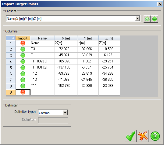
The settings of the import dialog must be configured to match the data ordering of the file being imported. First, ensure that the Delimiter is set to the correct value, if it is there should be multiple columns in the dialog, if it isn't, all of the data should only be in one column. After the delimiter is properly set, the data values for each column must be set. This can be done by clicking the header of each column (which say Click to Set by default) to bring up a menu with all the available values that can be set for that column. After setting these values toggle the importing of lines you wish to leave out by clicking the green buttons in the Import column to turn them red. At the top of the dialog is the presets panel, which will allow you to save the current settings if you wish to use them again later. After configuring the dialog to match your data, click the green check to import and continue to the next step. The next dialog displayed will allow you to configure the naming conventions for the target points to be imported.
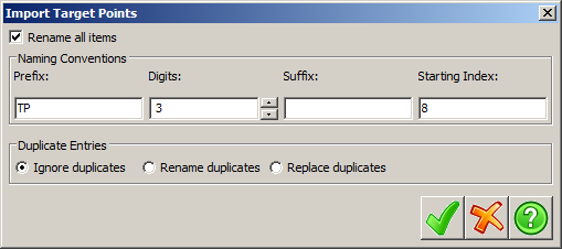
Selecting Rename all items will rename all imported points to the settings specified in the options. The Duplicate Entries panel will specify the action to take when a point being imported has a name that already exists in the set of points being imported to. If the Rename all items toggle is not selected the names listed in the file being imported will be used. If there are no names in the file being imported and Rename all items is not selected, the control points will be named using the settings in Project Settings naming conventions.
Clicking the export button will bring up the Export Target Points dialog, which will allow you to export the data to several different file formats.
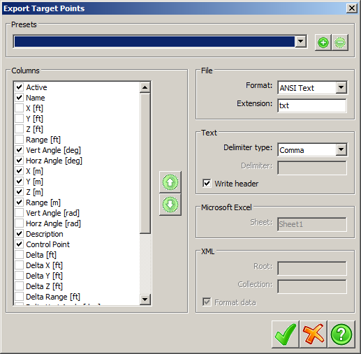
Simply click the check boxes next to the data elements that you
wish to export. To change the order of the data elements in the
file, select the data element you wish to move and click the up or
down arrow to move it.
The File panel determines which file format to
export to and also allows you to specify an extension other than
the default for a given file format.
The Text allows you to specify the
Delimiter to be used as the divider between data
elements in the file and whether to use the Write
header to specify whether to write a header line to the
file detailing the data ordering of the file.
The Transform Target points dialog box allows specifying a sequence of transformations to apply to the currently selected target points.
Initially the transformation list is empty. Press the green plus button to add a new transformation, which will bring up a new dialog.
There are three types of transformations, as well as an advanced transformation where the user can specify the transformation matrix to apply.
After the transformation's settings have been configured, pressing the green check mark will add it to the current list of transformations. In the Transformation sequence dialog the following functions apply:
|
|
Will allow you to edit the currently selected transformation. |
|
|
Will delete the currently selected transformation. |
 
|
Will change the order of applications of the transformations. Transformations are applied in top-to-bottom order. |
The Register Scan Position button will launch the Register Scan Position dialog box.
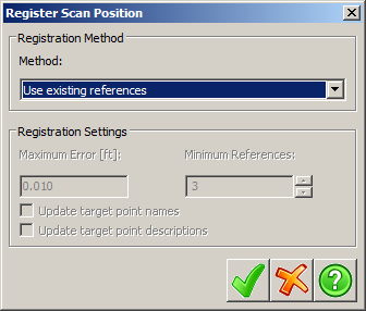
There are four registration methods; Use existing references, match point names, Match point descriptions and Minimize point position error. The Registration Settings are used with Minimize point position error only. The settings are grayed out for all other methods. Click the green check mark to register the target points. Once registration is successful you can check the results in the Edit Target Points dialog. The data displayed is controlled by the options selected in settings.
The Settings button will bring up the Point Editor settings dialog, which will allow the user to configure which data elements of the current point set are visible, as well as the order that they are displayed in.
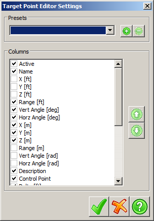
Display of a property can be changed by toggling the check box next to that property, changing the order can be done by first selecting the property to move and then pressing the green up or down arrows to move the selected property up or down. Saving the current settings can be done clicking the plus button in the Presets panel.
Tab Location(s): Project Tab
Panel and Button: Current Project and Target Points
Prerequisite: None