Selecting the Point button from the Create panel in the Action Tab will open the Create Point dialog. The Current Mode will be set to Point Creation.

The Snap Mode Panel offers twelve different options for snapping to points in the cloud in the open scene.

None - No snap function is active. The point will be placed at the cloud point nearest to the selected location.
Low - The point is placed at the lowest point (smallest z value) within the Snap Radius.
High - The point is placed at the highest point (largest z value) within the Snap Radius.
Low Edge - Snaps to the low edge of a feature, like a curb. A dynamic window in the upper left of the scene displays a cross section of the area within the Snap Radius and displays the high and low edge as red squares.
High Edge - Snaps to the high edge of a feature, like a curb. A dynamic window in the upper left of the scene displays a cross section of the area within the Snap Radius and displays the high and low edge as red squares.
Slope Bottom - Snaps to the bottom edge of a slope that is less than 45 degrees. This is useful for finding low edges on mountable curbs and other non-vertical features. Slope Top - Snaps to the top edge of a slope that is less than 45 degrees. This is useful for finding upper edges on mountable curbs and other non-vertical features. Average Point - This snap averages Northing, Easting and Elevation for all points within the Snap Radius and uses the averaged values for the coordinates for the new point.
End Point - Snaps the new point to the endpoint of an existing polyline.
Mid Point - Snaps the new point to the midpoint of an existing polyline.
Node - Snaps the new point to points placed in the drawing using Carlson Point Cloud Create Point.
Nearest - Snaps the new point to the point on an existing polyline nearest to the cursor location.
Feature points are specific types of features that Carlson Point Cloud can extract and list data for. These features are extract as 3D cylinders and other 3D elements to reflect the feature selected and display the general shape in the Point Cloud scene. The screen captures below show the various cylinders for each feature type. There are four options in the Feature point drop list.

None - No Feature type is selected.
Tree - The user picks a point near the bottom of a tree in the scene and the trunk diameter, height, and drip line diameter are extracted and displayed as the description for the point.

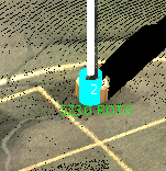
Pole - The use picks near the base of a pole in the scene and the diameter and height are extracted and displayed as the description for the point.
Hydrant - The use picks near the base of a hydrant in the scene and the diameter and height are extracted and displayed as the description for the point.

Use SZ Code - When toggled on this command will change the description displayed in the scene and stored in the Coordinate list. The new description is coded to take advantage of special codes in Field to Finish to more accurately display the features. Size or height, rotation and diameter or width. By setting up the Field to Finish file (.FLD) to place 3D blocks and use the special codes placed in the description by Point Cloud a more realistic and accurate 3D view can be created in CAD.
Hide Feature Points - When toggled on this command will "hide" or remove from the scene that points that make up the feature selected. For example, if feature type Pole is active and you select the base of a pole, the points that display as the pole in the scene will be hidden. A coordinate point is placed showing the diameter and height of the pole.Note: If the Hide Feature Points is toggled on and features are selected the user will be prompted to update the cloud, save a new cloud or discard changes when closing the scene.
The Create Point panel displays options for creating a point.

In the Create Point panel you can choose the destination of points created using the Active List drop list. Points created will be added to the list displayed in the Active List. Three options are available.
Point Number determines the number to be assigned to the point. There are two options for numbering.
Increment Current will follow the standard numbering convention of Carlson Civil Suite (increment the number without any filler digits).
From Settings will use the prefixes and digits from the naming Conventions in the Project Settings
Code will bring up the Point Cloud Code Table dialog.

Pick FLD File allows the user to set the current field-to-finish file (.FLD). Once an FLD file is open the user can select a code to use to create points by click the desired code and then clicking the Green check mark
The Field-to-Finish Linework panel allows you to specify properties of the next field-to-finish linework segment (if the current code table entry has linework associated with it). If your code does not specify linework you will receive a message that your code does not have linework associated. Once you clear the message dialog your point will be placed and the linework options will be set to None.

Once a code is selected from the Create Point panel the user may select one of the Field-to-finish Linework radio button options.
None no linework is created. This is the default when a Point code without linework is selected.
Start Line Begins a line using the parameters in the code table. Lines are only created for point codes that have linework associated with them.
Continue is selected as you continue adding points to the current field-to-finish linework.
Start Curve (PC) Sets the starting point for an arc. The arc will be drawn using the parameters in the code table.
Specify Vertex Position: Places a point at the selected location. If the point Code is associated with line work the point is connected to the previous point with a line.
Tab Location(s): Action Tab
Panel and Button: Create and Point
Prerequisite: An open scene of a point cloud