
HEC-RAS is designed to perform one-dimensional hydraulic calculations for a full network of natural and constructed channels. It could be considered to be an advanced Windows-based version of the HEC-2 program. This program makes it easier for CADD and GIS systems to import their data directly for river network analysis. It is also very convenient because the output from the program can be exported directly to CADD programs where this data can be used to create water surface models for inundation mapping. The software is free and can be downloaded from http://www.hec.usace.army.mil/software/hec-ras/.
In the program of Prepare HEC-RAS Input File, every channel is
defined by a cross-section file and a MXS file (please see the
material on Sections in Chapter 6 of this manual). This
program reads cross-section files and the corresponding MXS files,
and then creates a HEC-RAS geometry data file.
Data Format
HEC-RAS input files consist of three data sections:
* A header, containing data relevant to all sections of the data
in the file.
* A description of the stream network, containing reach locations
and connectivity.
* A description of the model cross-sections, containing
cross-section location and geometric data as well as additional
HEC-RAS modeling information.
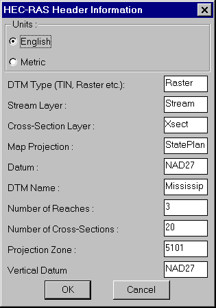
The header information is mainly for the purpose of identifying the project and is mostly not used by the program. The only important information needed by the program is the "Units" section and the value must be "ENGLISH" or "METRIC".
The network is modeled as a set of interconnected streams. Each stream is a set of interconnected reaches. Each reach, hence, MUST have a unique Stream ID and Reach ID.
The Stream Network section contains a series of Point Numbers and the corresponding coordinates. In addition, this section has information pertaining to each Reach. For each Reach, the following information is provided:
* Stream ID and Reach ID. These are 16 character alphanumeric
strings. Together these two items uniquely identify a Reach.
* Starting (FROM or upstream) point and ending (TO or downstream)
point of the Reach. The FROM point and TO point here are given by
their Point Numbers, as identified above.
* The coordinates on the Centerline of the Reach, starting with the
FROM point coordinates and ending with the TO point
coordinates.
The Cross-Sections portion of the input file contains data describing the geometric properties at each cross section in the network. The following information is provided at each Cross-Section:
* Stream and Reach ID, to identify which Reach the Cross-Section
is on.
* Station, position of the Cross-Section, relative to the Stream.
The Station is taken as the distance from the current station to
the end of the stream. For this purpose, the stream MUST be drawn
Downstream to Upstream. THIS IS THE MOST FUNDAMENTAL REQUIREMENT OF
THE PROGRAM. If the Stream is drawn in the other direction, then,
it must be reversed using the command Reverse Polyline under
Edit>Polyline Utilities
* Cut Line: Series of point coordinates, identifying the surface
line of the Cross-Section. HEC-RAS identifies the cross-sections as
going from left to right as seen from upstream to downstream. The
user only needs to make sure that the stream network is drawn in
the right direction (downstream to upstream); all other conventions
are taken care of by the program.
Modeling Guidelines
Some additional guidelines in drawing the river network in the CAD
so as to model correctly for HEC-RAS:
* All the Reaches in the Stream Network must be connected at common End Points; disjointed Stream Networks are not allowed; Reaches must also NOT cross each other.
* Streams cannot contain parallel flow lines. If three reaches connect at a node or End Point, at the most TWO of them can have a common Stream ID. (Please note that a Reach is uniquely identified by a Reach ID and a Stream ID.)
* Cross-Section lines can cross a Reach line only once and cannot cross other cross section lines.
Program Execution
Before starting the "Prepare HEC-RAS Input File" command, all the
SCTfiles and their corresponding MXS files should have been created
for every Reach. Points where two streams meet would form a node in
the stream network. Sections of a stream between such nodes should
be modeled as a Reach. and drawn as a separate polyline. Now,
change to the Civil Design Menu. The MXS file for each Reach is
created using the command Input Edit Section Alignment under
the Sections pulldown menu. Based on any of the methods for
creating section files (described in chapter 6 of this manual), the
Section file for the Reach is created. The user must manage the
.MXS file and the .SCT file corresponding to each Reach. At this
point, a Stream ID and Reach ID may be assigned to every Reach,
based on a convenient naming convention, which is entirely up to
the user. These IDs would be needed when creating the HEC-RAS input
file.
The program starts by asking the user for the Header
information. The user can input as much information in this dialog
box as possible. The "Units" can be "Metric" or "English".
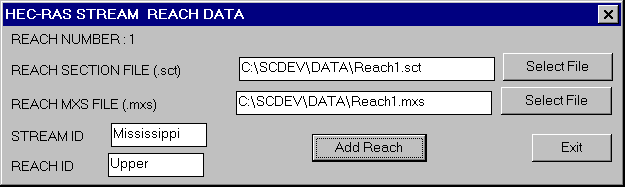
Next, the user will be prompted to enter the .MXS and .SCT file
names, the Stream ID and Reach ID for each Reach that you wish to
add to your model. The user can enter data (IDs and file names) for
as many Reaches as wished. That is, the user can create input files
for each Reach individually and import them individually into
HEC-RAS or create a combined input file for all the Reaches in the
Stream Network. This makes it very convenient to add more Reaches
to the HEC-RAS model at a later stage or do the analysis for
various sections separately. After entering as many Reaches as
needed, the user presses "Exit" to stop entering any further
Reaches and to continue with the program execution.
On pressing "Exit", the user is prompted for the Input HEC-RAS file to be created. HEC-RAS input files have a .GEO extension. When the file is chosen at the prompt, the program creates the input file for HEC-RAS. This file can be used to import geometric data into HEC-RAS, as described below. You must have HEC-RAS version 2.0 or higher installed on your computer.
After starting HEC-RAS, select "Geometric Data" from under the "Edit" pulldown menu to open the Geometric data editor, which has a CAD screen and various options. From the "File" pulldown menu on the Geometric data editor, run "Import Geometric Data -> GIS Format" command and select the .GEO file just created. This loads the geometric data into HEC-RAS and displays it in the form of a Stream network, with EndPoint, Stream ID and Reach IDs, Cross Sections stationing information, along with directions of in each Reach.
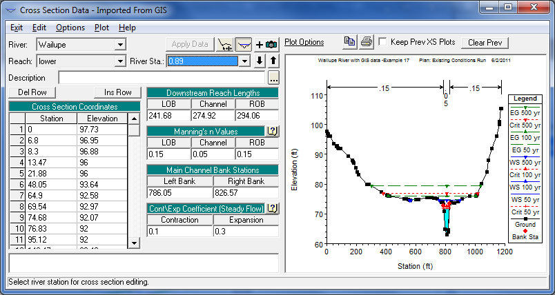
Since Carlson only provides default values, the cross section
data should be checked next. For example the manning's n, left over
bank and right over bank position, and the lengths of the left and
right over banks. By default, the left bank is given to be at 0.45
times the cross-section length and the right bank is given to be at
0.55 times the cross-section length. In order to correctly model
the channel geometry, the location of the banks must be accurately
defined for each cross-section. The left and right over bank
lengths are defaulted to the centerline length ( which may not be
equal in the case of a sharp bend in the stream).
Geometric data can be stored by running "Save Geometric Data" from the "Geometric Data Editor". The file extension assigned for Geometric data files is *.g*, which means that successive geometric data files will be given file extensions in a numeric sequence, beginning with *.g01.
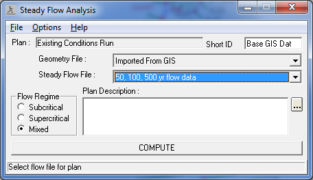
Flow data can be entered in the "Steady Flow Data Editor", which can be brought up by selecting "Steady Flow Data" from the Edit pulldown menu of the main HEC-RAS window. The data that can be selected here are the number of profiles that need to be run, flow in each reach for each profile simulation and the Hydraulic boundary conditions at each Reach for each Profile simulation. This information is stored in a file with the extension *.f01 and so on for successive files.
Once all the geometric data and flow data is entered, run command "Run->Steady Flow Analysis". After selecting the type of flow condition (sub-critical, super-critical or mixed), the user selects the "Compute" button to complete the analysis. If there are errors or serious warnings, the program reports them in a text editor. Otherwise, the program shells out to a DOS screen and completes all the necessary calculations. Several options are available for viewing and editing output from the HEC-RAS program, which are best explained in its manual.
Pulldown Menu Location: Watershed->HEC-Ras Water
Surface Model
Keyboard Command: sct2ras
Prerequisite: Section data (.sct)