

The Advanced Weir Design uses the methodology described in HEC-22 Manual. The weir flow is determined as:
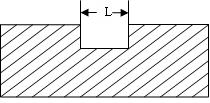
Q = Cw L H0.5 for the Rectangular Weir without Contracted End|
|
|
|
Rectangular Weir with Contracted End |
Rectangular Weir without Contracted End |
|
|
|
|
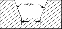
Trapezoidal Weir |
V-Notched Weir |
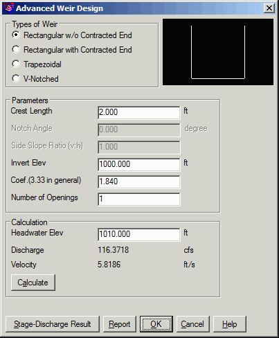
This command designs a weir structure and calculates its
stage-discharge curve. Select Weir Design from the Structure menu
in the Hydrology Module to display the design dialog. Select the
Type of the weir , Rectangular, Trapezoidal or V-notched. Enter the
dimension for the weir. In the Invert Elev box, type the absolute
elevation at which the weir will be attached to a reservoir. The
attachment point is at the bottom of the weir. In the Coefficient
box, type a weir coefficient value. In the Number of Openings box,
enter the number of weirs you want to combine.
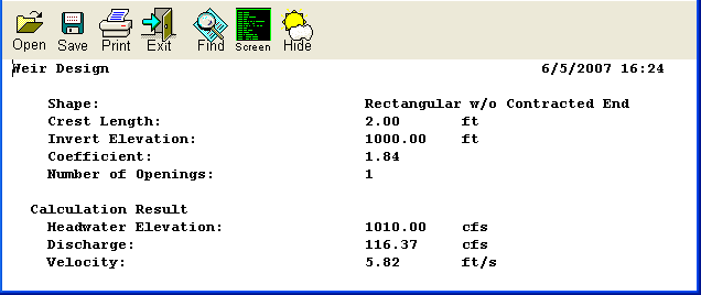
In the Headwater box, type the absolute headwater surface elevation. Click on the Calculate button, the maximum discharge and flow velocity through the weir would be computed and displayed.
Click on the Stage-Discharge Result button to display the
stage-discharge curve in the Stage-Discharge Result Dialog. This
dialog allows you to write the stage-discharge data to a
stage-discharge file(.STG), and draw the stage-discharge curve on
the screen. From the Stage-Discharge Curve Draw Settings dialog ,
you can specify how to draw the curve. The Report button generates
the weir design report.
|
| Advanced Weir Design
Dialog |
|
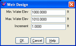
| Stage-Discharge Limits
Dialog |

|
| Stage-Discharge Result
Dialog |
|
| Weir Design Report |