This function assigns pre-determined sewer parameters for pipes and structures from selected 2D polylines that have been previously drawn to the screen, places the pipes at a pre-determined offset from the structure rim elevation and converts them to a Sewer (*.SEW) file. This command is very similar to the Import Sewer Network from 3D Polylines command and the Import Network from Centerline/Profile command. Sewer structures are inserted at the polyline vertices with the base elevation of the structure taken from the polyline vertex elevation. Pipes are created to replace the polyline segments and the invert elevations of the pipes also come from the polyline vertex elevations.
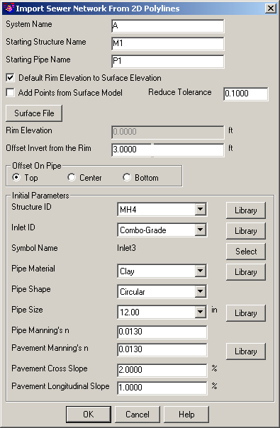
System Name: Indicate the system designation for the incoming sewer entities. A *.SEW file can have multiple systems (e.g. A, B, STRM1, STRM2, etc) within it.
Starting Structure Name: Indicate the designation that is to be assigned to the first structure (i.e. a junction) to be created by the routine.
Starting Pipe Name: Indicate the designation that is to be assigned to the first pipe that will be created by the routine.
Default Rim Elevation to Surface Elevation: When enabled, this option allows you to click the Select File button indicate a valid Carlson surface file (generally created through the Triangulate & Contour command) as the source for the new rim elevations.
Add Points from Surface Model: When enabled, this option inserts additional junction points along the 2D polyline where it crosses the triangulation legs of the surface model.
Reduce Tolerance: Identify the smallest tolerance to which new points should be added to the 2D polyline.
Rim Elevation: Indicate a single desired rim elevation to be applied to all new structure locations.
Offset Invert from the Rim: Indicate a vertical offset distance rim elevation for the placement of the pipe.
Offset on Pipe: Indicate a the location on the pipe to be used for the pipe offset:
Structure ID: Indicate the type of structure to be used for the new sewer data or click on the Library button to access the Sewer Structure Library command to create a new structure definition or edit an existing structure definition.
Inlet ID: Indicate the type of inlet to be used for the new sewer data or click on the Library button to access the Inlet Library command to create a new inlet definition or edit an existing inlet definition.
Symbol Name: Use the Select button to access the symbol selector of the Symbol Library command to access a desired symbol for the structure.
Pipe Material: Indicate the type of material to be used for the new pipes or click on the Library button to access the Pipe Material and Manning's n-Library command to create a new pipe material or edit an existing pipe material definition.
Pipe Shape: Indicate the general pipe shape that is to be applied to the new pipes.
Pipe Size: Indicate the desired pipe size for the new pipes or click on the Library button to access the Pipe Size Library command to create a new pipe size or edit an existing pipe size definition.
Pipe Manning's n: Indicate the desired Manning's n-value to be applied to the new pipes.
Pavement Manning's n: Indicate the desired Manning's n-value to be applied for runoff considerations or click on the Library button to access the Pavement Manning's n-Library command to create a new Pavement Manning's n-value or edit an existing Pavement Manning's n-value definition.
Pavement Cross-slope: Indicate the desired pavement cross-slope for ponding width calculation purposes.
Pavement Longitudinal Slope: Indicate the desired pavement longitudinal slope for ponding width calculation purposes.
Select 2D polylines.
Select objects: Select the desired 2D polylines that are to be converted
and press Enter when complete. If several polylines are met at one
vertex, only one structure is created, and the first polyline is
the main flow line, others are the upstream branches.
The sewer network will be drawn on the screen as the routine completes and can be manually drawn later through the Draw Sewer Network > Plan View command.
Pulldown Menu Location(s):
Network > Sewer Network
Utilities
Keyboard Command: swr2dp
Prerequisite: 2D polylines drawn on screen