|
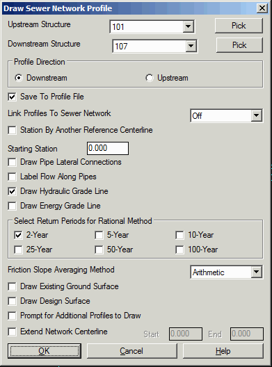
| Draw Sewer Network Profile
Dialog |
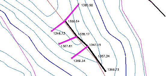
Consider the Sewer Trunk Line shown
in the plan view below:
This command will read the active sewer network (.SEW) file,
which contains inverts elevations, rim elevations, pipe sizes and
structure dimensions, and draw the network as a profile, using the
standard prompting in Draw Profile. In the options dialog, you can
select the structure names for the start and end of the profile and
set the profile direction as either upstream or downstream. The
Save To Profile File option
will save the sewer profile to a .pro file in addition to drawing
the profile. When the Save option is active, there is an option
available to Link Profiles To
Sewer Network. This Link option will update the sewer
profile drawing whenever the sewer network is modified. Also, this
link option will update the sewer network if the profile is
changed. For example, if Input-Edit Profile is used to change an
invert elevation and the link option is active, then the invert
elevation will also be updated in the sewer network. If you have a
road and want to use it to reference the sewer network, you can
choose the Station by Another
Reference Centerline to do that. When not using a reference
centerline, the Starting
Station value is used for the beginning station of the sewer
profile. Draw Pipe Lateral
Connections will draw ellipses at the profile structures for
any additional pipes that connect to the structure. Label Flow Along Pipes option pulls out
the total flow that runs through each pipe and labels it on the
profile. Draw Hydraulic and
Energy Grade Line option
records the hydraulic flow calculation result and draw hydraulic
and energy grade lines with network profile. You may choose to draw
HGL/EGL for multiple storm events. The Draw Existing Ground Surface and
Draw Design Surface options
will prompt for a surface file and then extract a profile from the
surface to draw with the network profile. If you have other
profiles to draw along with the network as a reference, such as a
road profile, turn on the Prompt
for Additional Profiles to Draw option. Extend Network Centerline lengthens the
sewer network centerline by the specified amounts for extracting
the surface profile for the existing and design surfaces.
|
|
| Draw Sewer Network Profile
Dialog |
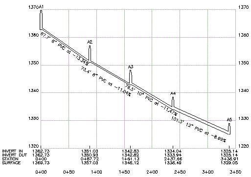
When this network main sewer line is entered using Locate Sewer
Structure, starting at the upstream rim elevation of 1369.73 and
running downhill to 1328.54, a new .SEW file is created. Prompting
asks you to select a starting structure. If you created 5
structures named A1 through A5, you could choose A1 to plot all 5.
This file will then plot, in profile view, as shown below (this
example was drawn without ground surface or hydraulic grade lines).
If you pick Draw Existing Ground Surface, you will be
prompted for the grid or triangulation file for the ground surface,
and similarly if you turn on Draw Design Surface.
|
|
| Profile view of Sewer Network |
Pulldown Menu Location: Network->Draw Sewer
Network
Keyboard Command: drwswrpro
Prerequisite: Sewer network (.SEW) file