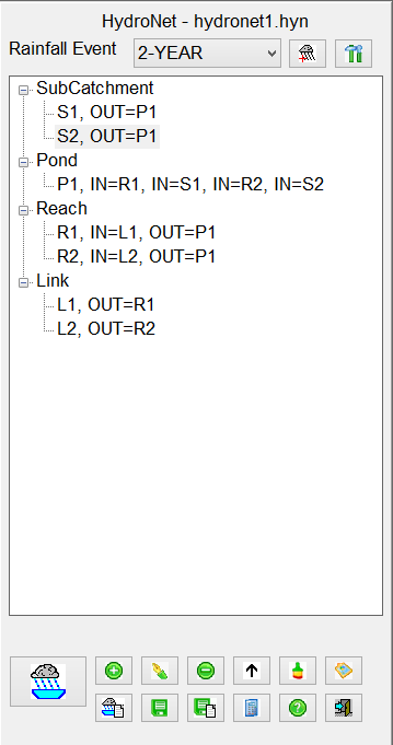
HydroNet Explorer
HydroNet Explorer is a powerful stormwater modeling program that
designs and analyze simple and complex watershed networks. In the
program, you define a hydrologic network by building a collection
of hydrologic nodes. There are four types of nodes: subcatchment,
pond, reach and link.
The general idea for the use of the HydroNet Explorer is that
you have already prepared a drawing for analysis.
This preparation would include:
Soils: The boundaries of the Hydrologic Soils Groups should be
drawn on the drawing layer specified in the Watershed Layers
dialog, with the A, B, C, or D labels on the layer specified for
that. These areas do not have to be closed polylines, as long
as the linework encloses each area that is part of the
study.
Ground Covers: The various Ground Covers in the study area
should be drawn as closed polylines on the layers specified in the
Watershed Layers dialog. These do not need to be
labeled.
Watersheds: The Watersheds (subcatchments) for the site
should be drawn and labeled. It is best to do this with
closed polylines, but it is not essential, as you can use an
alternative method of picking within the area and having the
software define it from drawing linework.
When you run the HydroNet Explorer command, you
are prompted to create a new .HYN file or open an existing
one. This is the file that stores all of the data about the
components in the project.
Project Settings
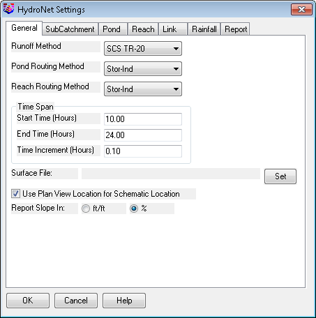
Once the HydroNet Explorer is open, the first thing you should do
is check the settings for the current project. Pick the icon
with the tools on it. In the HydroNet Settings dialog, review
the various tabs containing the settings for the different aspects
of the project.
On the
General tab, choose Runoff Method, Pond Routing
Method, and Reach Routing Method. Set time span. Set the surface to
be used to provide the average slope for each subcatchment when
using the Curve Number/Lag method.
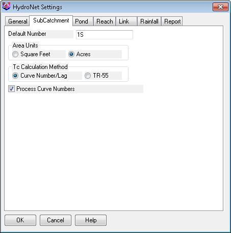
On the
Subcatchment tab, set the default starting number for
subareas, the default method for Tc calculation, and also set
whether Curve Numbers should be calculated in Carlson Hydrology
(check the box) or in HydroCAD (uncheck the box).
On the
Pond,
Reach and
Link tabs, set the
default starting number for each of these components.
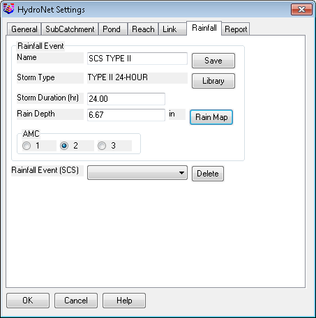
Rainfall Tab
If you want rainfall to be added to the calculations in Carlson
Hydrology, set up the rainfall parameters here. If you want
the rainfall data to be added in HydroCAD, you can ignore this
tab. Detailed information about setting up Rainfall events in
Carlson is under the Watershed section of the Carlson
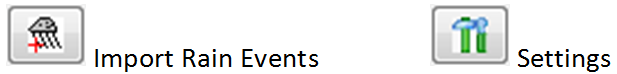
documentation. There is also an icon at the top of the
HydroNet Explorer that you can use to import a Rainfall event from
a HydroCAD project file.
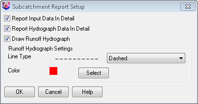
Report Tab
On the Report tab, establish the type of report and the details of
the report that you want for each of the 4 component types. Each
setup button allows for reporting options in detail, drawing option
such as colors, and linetypes.
Subcatchment
Subcatchment contains the watershed conditions. Once the
watershed layer file is defined by the command Define Watershed
Layers, the program can automatically pull out the watershed data
and fill all the values. There can unlimited numbers of
subcatchment in the network, which are divided by the watershed
boundary polylines.
You can now use the HydroNet Explorer to automatically analyze
the drawing and add all subcatchments defined in the drawing.
Pick the Update button, and check all of the options. With
the dialog set up as shown, when you pick OK, all subcatchments
found on the specified layer are added to the Explorer and exported
to HydroCAD. The detailed data for each subcatchment can now
be viewed and/or edited. Double click on any subcatchment to
edit.
To add Subcatchments manually, pick on the Subcatchment item in
the Explorer, and either right click and pick add from the submenu
or pick the Add icon.
In the Subcatchment dialog, enter the Number for the
Subcatchment. If you have the Subcatchment labeled in the
drawing, make the Number match the label. Pick the Edit
button next to the Area. In the Sub Areas dialog, pick the
Select Subcatchment button. Carlson Hydrology searches for a
subcatchment on the layer specified in the Watershed Layers dialog
that has a label that matches on the specified layer that matches
the Number. If it finds one, it highlights it and asks you to
confirm that this is the Subcatchment you are meaning to use.
If you pick Yes, the SubAreas are calculated from all of the
additional data in the drawing. Pick OK. Back in the
Subcatchment dialog, if you specified the CN/Lag method for Tc, the
Average Slope of the Subcatchment has been calculated and
displayed, and the longest polyline within the subcatchment on the
specified layer as been selected and it's length displayed.
Pick OK. The new Subcatchment is listed in the Explorer.
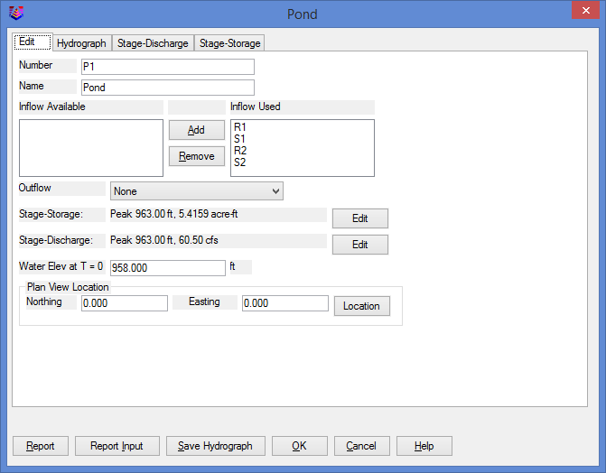
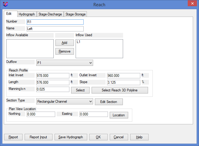
Pond and Reach
Pond acts as a storage and routing element in the network, and
Reach is a routing element. The upstream node of pond and reach
generates a hydrograph. The procedure to add Ponds and Reaches is
similar to Subcatchments, either right click and pick Add, or
select the category heading and pick the Add button below.
The detailed documentation on inputting data for these component
types is found in the Watershed section of the Carlson Hydrology
documentation.
Link
Link is used to model a hydrograph or a sewer network. This program
assumes that the hydrologic network is a linear system, and allows
two hydrographs to be superposed by adding the two given flows at a
specific time step. In the network two or more hydrographs are
combined at a node by allowing multiple links to discharge to one
downstream node.
The procedure to add is similar to Subcatchments, either right
click and pick Add, or select the category heading and pick the Add
button below.
Export to HydroCAD
If you are using HydroCAD in conjunction with Carlson Hydrology,
once the elements of the study are added to the HydroNet Explorer,
pick the Export to HydroCAD button to transfer the data to
HydroCAD.
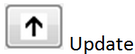
 Any changes
made in the drawing that affect any of the components of the study
can be instantly updated and sent to HydroCAD with the Update
button in the HydroNet Explorer. Also, each individual
component can be updated alone with the update button within it's
specific dialog box.
Any changes
made in the drawing that affect any of the components of the study
can be instantly updated and sent to HydroCAD with the Update
button in the HydroNet Explorer. Also, each individual
component can be updated alone with the update button within it's
specific dialog box.
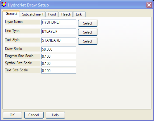
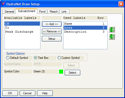
The components listed in the HydroNet Explorer can also be drawn
into the drawing file with the Draw Layout in CAD button
(paintbrush). Set the desired parameters in the HydroNet Draw
dialog box.
Pulldown Menu Location: HydroCAD
Keyboard Command: hydronet2
Prerequisite: Soils, soil labels, watersheds, watershed
labels, a TIN, and Ground Covers, all on different layers for the
different areas.