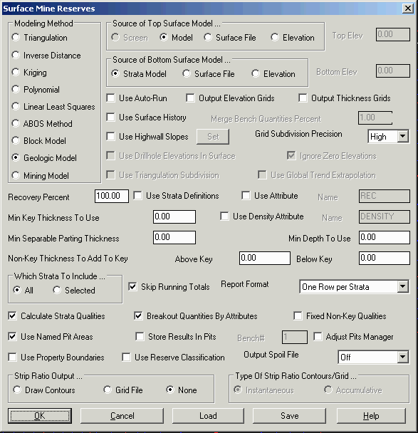
Surface Mine Reserves
This command calculates quantities and qualities from drillholes
or predefined grid or block models. Strip ratios can also be
calculated as the volume of non-key strata divided by the tons of
key strata. Key strata are intended to be the target ore, and
non-key strata are intended to be the overburden, interburden and
parting strata. Within the drillholes or Geologic Model file, each
strata has a field that specifies whether the strata is key or
non-key. Volumes can be stored in the pits for scheduling with this
command. There are many options for reserve calculation and they
are detailed in order of appearance below.
- Modeling Method: The
surface reserves can be generated on-the-fly from the selected
drillholes or read from stored grid files put into a Geologic Model
file. The on-the-fly modeling method can be either Triangulation,
Inverse Distance, Kriging, Polynomial or Linear Least Squares. An
explanation of these different methods is found under Make Strata
Grid Files. The Block Model option creates a BLK block model file
and calculates reserves "on-the-fly". The stored grid file method
is the Geologic or Mining Model options. The Geologic and Mining
Model methods use prepared grid files that represent the bottom
elevation or thickness and quality attributes (i.e. BTU) of the
strata. The grid files associated with each strata and the ground
surface are set in the Define Geologic Model or Define Mining Model
commands. The difference with the models is that the Geologic Model
has the strata elevation grids unadjusted for mining methods from
the Surface Mine Reserves settings such as Recovery Percent. The
strata elevation grids in the Mining Model already have these
adjustments applied. So when the Mining Model method is selected
the adjustment parameters like Recover Percent are disabled in the
dialog because they have already been applied in the
model.
- Source of Top Surface
Model...: Surface Mine Reserves works from the top strata
down to the bottom. The ground surface is modeled from either the
Screen using selected surface entities, the surface grid found in
the Geologic Model file, a separate grid file (something different
than the surface grid in the Geologic Model, such as a top of bench
grid) or an elevation. This elevation could be the elevation of a
flat bench that represents the top of the reserve calculation
interval. In the Screen method, the program builds a grid model
from the selected entities (contour polylines, points and 3D
entities). See the Make 3D Grid File command for a description of
creating a grid file. The "Source of Top Surface Model" option sets
this ground surface method. Each strata structure is modeled as the
bottom elevation of that strata. The strata volume is figured by
comparing the strata bottom elevation model with the previous
strata. The first strata bottom elevation is compared with the
ground surface grid. Each strata grid clips to the grid above so
that the strata grid does not rise above the previous grid which
includes the ground surface. The result is that the program will
find strata outcrops if any.
- Top Elev: When using
the Elevation method in the Source of Top Surface Model, this is
the elevation that controls the top of the structure or reserve
block. Enter in any elevation.
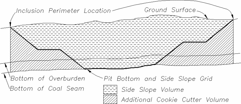
- Source of Bottom Surface
Model...: Carlson can either calculate quantities straight
down from the inclusion polylines ("Cookie-Cutter") or apply side
slopes. There are two methods for modeling the side slopes: using a
bottom surface grid or highwall slopes (explained below). Without
either of these methods, the program will calculate the strata
quantities straight down vertically from the inclusion perimeter.
In all cases, the strata quantities are limited by the ground
surface grid or elevation which effects the top strata and outcrops
any other strata. The Strata Model option will calculate down to
the lowest grid in the Geologic Model, or the lowest grid in the
Selected Strata option, if that is used. The Grid File method will
go down to this grid for reserve calculations. It can have any
number of benches and slopes in it. This method will prompt you for
a grid file which should represent the bottom of pit surface
including the side slopes. This grid file should have the same
position and resolution as the surface grid. Keep in mind that the
grid resolution should be small enough to model the pit side
slopes. For example, a 100 ft grid interval would not work well for
modeling side slopes that are 30 ft wide. Instead, use a grid
resolution that is smaller than the side slopes width (i.e. 10 ft
in this example). There are many routines for preparing the pit
bottom grid including the Design Bench Pit routine and Make 3D Grid
File. Typically the inclusion perimeters should start from the
daylight line where the pit bottom grid intersects the surface
grid. The program will calculate the strata quantities between the
surface grid or elevation and the pit bottom grids. The last option
is Elevation. It allows for entering an elevation to represent the
base of the reserve "block". If using Elevation for the Top Surface
Model, and Elevation for the Bottom Surface Model, it will
calculate the various quantities within the two elevations that
could represent benches. Shown below is an example of the Source of
Bottom Surface Model as a Grid File.
- Bottom Elev: When using
the Elevation method in the Source of Bottom Surface Model, this is
the elevation that controls the bottom of the structure or reserve
block. Enter in any elevation.
- Use Auto-Run: This
option will prompt for the SMR auto-run file so that all of the
benches, strata and elevations are predefined beforehand, and all
benches can be run at one time and stored in the pits for
scheduling and reporting.
- Output Elevation Grids:
Turning this option on will create grid files for the bottom of
each strata found in the drillholes. Each grid needs to be named
separately. The command Make Strata Grids is a better way to create
these grids.
- Output Thickness Grids:
Turning this option on will create thickness grids of the strata
calculated for the current bench. It will prompt to create an
overburden thickness grid, a key thickness grid and a key tons grid
(tons/sq ft. or m). These grids will also be stored in the pits, if
Store Results in Pits is activated. The difference is that timing
using the actual numbers will average the quantities over pit area
while the grids will model the thickness within the pit so that
timing through a shallow end of the pit will be faster than the
deep end. Within Output Thickness Grids, there is an option to
divide the bench by thickness. This option will split the non-key
volume at the specified thickness into two benches. For example, if
you have 50 feet of overburden and one piece of equipment will
remove the first 10 feet while a second removes the rest, then set
the divide value at 10 feet and it will divide the first overburden
into two benches.
- Use Surface History:
This option will use the series of grids stored in a grid sequence
file (.GSQ) for bench volume calculations. The first grid in the
file is used as the starting surface grid and the second grid is
used as the bottom grid. The program calculates the strata
quantities and qualities using these two grids. Then the program
repeats this time using the second grid as the surface grid and the
third grid as the bottom grid. Again the strata values are
calculated using the next two grids. This process repeats until the
last pair of grids in the sequence file. The purpose of this
routine is to calculate the strata values at different mining
stages or benches. These benches are reported separately in the
final report. One routine that prepares the grid sequence file is
Design Bench Pit. If the Store Results in Pits is selected, these
benches are automatically assigned to the pits for timing.
- Merge Bench Quantities
Percent: This option is active when using the Surface
History File. If there are quantities less than the entered
tolerance percent, then they are merged into the associated bench.
This eliminates the error where a grid cell is crossing over from
one bench to another.
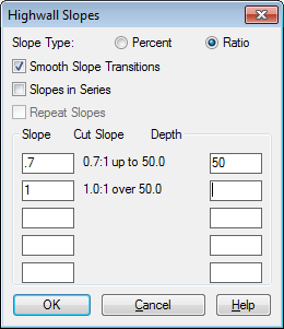
- Use Highwall
Slopes: This method applies the side slopes
on-the-fly. The slopes to use are specified under the Set Slopes
button. In this method, the inclusion perimeters should go around
the base of the pit. The program will apply the side slopes from
the inclusion perimeter up to the surface starting at the elevation
of the bottom strata. The daylight perimeter and any bench lines
are drawn as 3D polylines. This will only use depths up from the
bottom for changing slope, and is used when just reserving for one
total bench. If more complex benching is needed, then the Use
Surface History is the preferred method, created with Design Bench
Pit.
- Grid Subdivision Precision: This controls how much the
program subdivides grid cells during calculations at borders like
the pit inclusion perimeter. Set this to High for most accuracy.
Set this to Low for speed on rough calculations.
- Set Slopes: When using
the Highwall Slopes option, this button brings up the Highwall
Slopes dialog. Slope can be entered in as Percent or Ratio. The
Smooth Slope Transitions is "all or nothing". using the slopes
shown, if the depth was 60, then the entire slope would be 1.5:1.
The Slopes in Series option is more for benching. Using the slopes
shown below, 0-50 will always be 1:1. Once the depth gets above 50,
it will switch to a 1.5:1 and so on. Using Slopes in Series will
allow for Repeat Slopes, until it gets up to the surface. There are
only 5 different rows available to enter in the slope
template.
- Use Drillhole Elevations in
Surface: This option only applies if one of the modeling
methods are chosen and not Geologic or Mining Model. The drillhole
surface elevations should be used if they enhance the surface topo,
but if they differ from the surface contours or points, then they
should not be used.
- Ignore Zero Elevations:
This option only applies when using the entities on screen to
create the surface. Unless the mine is down near sea-level, zero
elevations should normally be ignored.
- Use Triangulation
Subdivision: This option only applies to the modeling
methods of Triangulation and Polynomial. It subdivides the
triangles to create smoother surfaces and ensure that contours do
not cross.
- Use Global Trend
Extrapolation: This also applies only to Triangulation and
Polynomial. This option finds the average slope and direction of
the existing data and applies this slope to extrapolating where
there is not surface data. .
- Recovery Percent: This
window defines the percentage of Key strata volume that was
recovered in mining and to include in the volume and strip ratio
reporting. The non-recovered key strata is added to the NonKey
volume. The recovery percent in the Surface Mine Reserves dialog
applies to all the Key strata. Enter in as 100 or 95.4 or 92,
etc.
- Use Strata Definitions (for
Recovery): To have different recoveries for each Key strata,
use Define Strata to create a strata definition for each Key strata
with the appropriate recovery percent. Then run Surface Mine
Reserves and click on Use Strata Definitions.
- Use Attribute (for Recovery):
Another recovery method is to
have a strata attribute for recovery. This allows for different
recovery percents at different drillholes. Then the recovery is
modeled for the area. The name of the recovery attribute is
specified in the dialog. This attribute will need to appear in the
drillholes for modeling on the fly, or in the Geologic Model as a strata attribute, with
the name spelled as it appears in the Name window to the
right.
- Name (Attribute): This
is the name of the recovery attribute that will be referenced when
using the Use Attribute option for recovery percentage.
- Min Key Thickness To
Use: This
option adds key strata to the nonkey strata above, in areas that
have thickness less than the specified minimum thickness. Also
areas with thickness less than the minimum are not counted in the
reported strata area.
- Use Density Attribute:
The strata density can be defined at different levels from general
to specific and the program will use the most specific density that
is found for the strata. The most general density setting comes
from the current drillhole definition file (.ch) as set with the
Define Drillhole command. The next level is the density setting
that is stored in each drillhole. To check a drillhole density, use
the Edit Drillhole command, the Key density is displayed in the
bottom of the dialog. The next level is strata specific density
that can be assigned with the Define Strata command. The most
specific level of density definition is the "Use Density Attribute"
option shown here in Surface Mine Reserves. This option models the
strata density using the strata attribute with the user-specified
name for density (i.e.. "Density"). Not only does this method use
the modeled strata density when averaging the strata quantities
with other strata, but the modeled density is used within the
strata to weight average that strata qualities. For example, if the
strata is more dense in one area, then the qualities such as BTU in
this area with be weighted more heavily. This can be changed if
desired, under Attribute Options in the Report Formatter.
- Name (Density): This is
the name of the Density attribute that will be referenced when
using the Use Density Attribute option for recovery
percentage. This must be spelled exactly as it appears in the
drillholes or Geologic Model file.
- Min Minable Parting
Thickness: This setting will add the non-key parting
quantities with the key quantities when the non-key parting
thickness is less than the specified amount. For example, if the
Min Minable Parting is set to 0.5, then a non-key strata between
two key strata would be combined with the key in areas where the
non-key thickness is less than 0.5 feet. In areas where the
thickness is greater than 0.5, the non-key quantities are not
adjusted. Combining the non-key quantities to the key will add to
the total key tons and affect the strip ratio. If the non-key
strata has qualities (i.e. ASH, Sulfur), then these non-key
qualities will be composited by nonkey tons with the key tons for
the portion of non-key that is less than the minimum parting. This
will dilute the key qualities.
- Min Depth To Use: The
Minimum Depth to Use option adds key strata to the overburden in
areas that have depth less than the specified minimum depth. For
example, if any Key strata are closer than 10 feet to the surface,
then they can be considered "weathered" and reported with the
NonKey waste material.
- Non-Key Thickness To Add To
Key: Above Key/Below Key: These fields allow you to specify
the amount of non-key thickness above and/or below the key strata
that will be combined with the key (roof and floor dilution) This
amount will be taken from the non-key quantities and added to the
key. Similar to the Min Minable Parting Thickness, the non-key
quantities will increase the total key tons which affects the strip
ratio and key volume mined. Also any non-key strata qualities will
be combined by thickness, weighted by NonKey density, and added to
the key which dilutes the key qualities. For example, if you
estimate that 0.25 feet on average of the overburden is taken with
the coal, then you could set the Non-Key to Add to Key for Above to
0.25.
- Which Strata To
Include...: This determines what will be calculated for the
reserve. If All is chosen, then all strata in the drillholes or
Geologic Model file will be calculated and reported. If Selected is
chosen, then the next window to appear is where one or multiple
strata can be selected. This can be used for multiple reserve runs,
selecting different strata to represent each bench.
- Skip Running
Totals: This option skips the running total quantities
and strip ratios for the strata. If it is not selected, then the
total for each pit is added to the next for a "running total"
quantity. If it is checked, then the pits are totaled separately,
and with a grand total at the end of the report.
- One Row Per Strata:
This is the standard format that comes up. It put each strata on
its own row in the report.
- All Strata on Same Row:
This option puts all the strata quantities and qualities for each
pit polyline on one row. This format is best suited for only a few
strata and for printing landscape on a page. If it is not selected,
then each strata will appear on a separate row.
- Group Key/NonKey Pairs:
This option will put an overburden/interburden strata on the same
row as the key seam. It looks for similar naming in the Geologic
Model file. Example that will group them together are: C1_OB and
C1_KEY, or C2_TOP and C2_KEY. All of the attributes for that
grouping, as well as discard will be put on the row also.
- Calculate Strata
Qualities: This
toggle will report the average qualities for strata attributes such
as BTU and sulfur. Otherwise the program skips calculating
qualities to save time. Besides reporting the qualities for each
strata individually, the program can also report the total averaged
qualities. By default, the qualities are weight averaged by tons
which are calculated by using the strata volume and density.
- Breakout Quantities By
Attributes: This feature works in conjunction with the
Block Modeling and Grade Parameter file. Once the BLK file
has been created, and the grade parameter file defined, they are
used in this reserve routine to calculate the volume of material
falling in certain ranges. For example, Surface Reserves will
report tons of ore with calcium of 80-90, tons of ore with calcium
90-100, etc.
- Fixed Non-Key Qualities:
This option will prompt to enter one value for each strata
quality found in the drillholes or Geologic Model to use for all
non-key strata. This option is useful in the case for calculating
the composite key strata qualities when there is key strata
dilution from non-key strata due to Min Minable Parting.
Prompts will look like:
- Non-Key value for BTU: 1000
Non-Key value for MOIST: 35
Non-Key value for SUL: 7
Non-Key value for ASH: 50
Non-Key value for DENSITY <80.00>: 155
- Use Named Pit Areas:
The area for calculating quantities defaults to the limits of the
selected surface entities and drillholes if no inclusion perimeters
are selected. To control the calculation area, multiple closed
polylines for areas to include and/or exclude can be selected. An
unnamed pit polyline will limit the area of calculations. Also,
areas can be labeled with site and pit names (i.e. Site 1, Pits
101, 102, ...). Surface Mine Reserves will then calculate the strip
ratios and volumes for each site and pit area. To use site and pit
names, there are several commands for creating named pit polylines
in the Boundary menu of Surface Mining. If this is selected, then
it will look just for named pit polylines, ignoring anything
else.
- Store Results In Pits:
This option is available when named pit polylines are used. This
option will store the total non-key volume, key volume and key tons
and all quality attributes for each pit polyline as extended entity
data to the pit polylines. These quantities can then be used by the
Surface Equipment Timing command. Besides the quantity and quality
values, a Bench number is also stored with the quantities for
sequencing each bench. For example, if you have two key and nonkey
seams that you are going to mine in two passes, then use the
Which Strata to Include: Selected option and choose the
first pair of NonKey/Key strata with the Bench# set to 1. Then run
Surface Mine Reserves a second time with the second pair of
NonKey/Key strata and the Bench# set to 2. The quantities
calculated can be stored either as values or as thickness grids for
scheduling. The grid option is activated by the Output Thickness
Grids option, otherwise it will store the values in the pits. The
difference is that timing using the actual numbers will average the
quantities over pit area while the grids will model the thickness
within the pit so that timing through a shallow end of the pit will
be faster than the deep end. Within Output Thickness Grids, there
is an option to divide the bench by thickness. This option will
split the non-key volume at the specified thickness into two
benches. For example, if you have 50 feet of overburden and one
piece of equipment will remove the first 10 feet while a second
removes the rest, then set the divide value at 10 feet and it will
divide the first overburden into two benches.
- Bench#: Enter in the
Bench number to assign for this "run" of Surface Reserves. Usually
Selected Strata is used with this, to select the strata to assign
for each bench number reserve run.
- Use Property
Boundaries: Property boundaries can be used to break up the
reserve by owner and property. The commands for laying out property
boundaries are in the Boundary menu. Essentially, property
boundaries are closed polylines with owner and property ID names.
The property polylines do not need to be clipped with the
calculation inclusion perimeter or pit polylines. The program will
internally clip the properties with the calculation areas and
report the amounts by property within each pit area. If a pit or
inclusion polyline is not covered by a property, the property name
used for these quantities is "unknown". To activate property
boundaries, click on the Use Property Boundaries toggle and the
program will search and find them automatically.
- Use Reserve
Classification: Using this option will prompt for an RSV
file created with the separate command Reserve Classification under
Grids in the Geology Module. This will separate the reserve into
Measured, Indicated, Inferred and Hypothetical, based on what is
entered in the RSV file.
- Output Spoil File: This
option gives the option to create a spoil file. There are 3
options, Off, Nonkey Only and All Strata. Normally, the spoil would
include just the Nonkey waste material. This creates a spoil
placement file (*.SPO) that is used for the timing of the spoil
routines under the Spoil Menu of Surface Mining.
- Strip Ratio Output: The
Draw Contours option will contour the total strip ratios of all the
processed strata (NonKey volume : Key tons). The program will
create the contours from a grid file of the calculated strip ratio
values. If you just want the grid file and not the contours, choose
the Grid File toggle and the program will prompt for a grid file
name to create.
- Type of Strip Ratio
Output: There are two methods for making the strip ratio
grid and contours. The Instantaneous option will calculate the
strip ratio using the strata thicknesses of the vertical strata
column at each grid corner. The Accumulative method will start with
the lowest strip ratio in the calculation area and keep adding the
next best strip ratio areas, basically an accumulative strip ratio
of the selected areas of the mine site. The grid file is assigned
the running strip ratio as the program adds these areas.
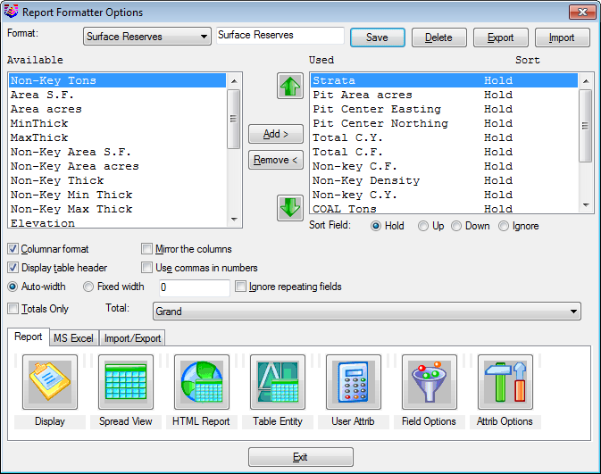
The Report Formatter Options dialog is the final step of the
Surface Reserves routine. It is documented elsewhere in the Help
manual for more details on its operation.
- Parent/Child Strata Split Quantities: If there are two
children seams in the Geologic Model file, and they come together
with no parting, then the program will automatically report them as
the parent seam name. This splitting must first be defined in the
Define Strata command (SDF File). The same names for the split
defined there, must also be used in the Geologic Model file for
strata names.
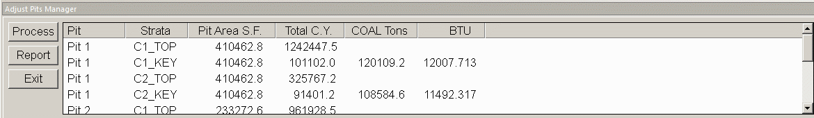
- Adjust Pits Manager: This option docks a manager dialog
at the bottom of the drawing. This dialog shows the reserve
results. You can then make edits to the pit perimeters using any
CAD function like move or grip edit. Then use the Process button to
recalculate the quantities and update the results. Use the Report
button to output the results or to change the format for the report
in the dialog.
Prompts
Surface Mine Reserves dialog
Select surface entities and at least 3 drillholes. (Unless
using a Geologic Model File PRE.)
Select objects: select the drillhole symbols and surface
entities. Surface entities can include points, lines, and
polylines.
Select the Inclusion perimeter polylines and ENTER for none:
Select objects: select the polylines or named pit
polylines. The area within these polylines will be included in
the calculations. They must be closed polylines.
Select the Exclusion perimeter polylines and ENTER for none:
Select objects: select the polylines. The area within
these polylines will be excluded from the calculations. They must
be closed polylines.
Make Grid File Set grid resolution
Triangulating points ... 49
Pass> 6 NULL Z values left> 0
Processing cell 2500 ...
Finished strata Y2
The above four steps are repeated for each strata.
Report Formatter
Pulldown Menu Location: StrataCalc or Reserves/Timing
Keyboard Command: mtntop