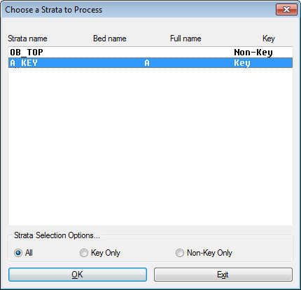
 The command Selected Strata Quantities brings up
this screen to select the strata or bed to analyze.
The command Selected Strata Quantities brings up
this screen to select the strata or bed to analyze.Two Types of Compositing are described here. (1) Single Seam or Ore Body compositing where the seam has been sampled at various intervals, and (2) Combinations of Several Seams Separated by Interburden.
(1) Single Seam or Ore Body
Large ore deposits such as limestone and thick beds of coal are often sampled at multiple points within the single ore body or bed. For long-range planning and reserve estimates, it is often desired to obtain the composite quality for the entire mineral deposit within an inclusion perimeter. For short-range planning, the mine engineer needs to know what quality will be obtained in a particular vertical segment of the ore body or seam, also within a defined perimeter.
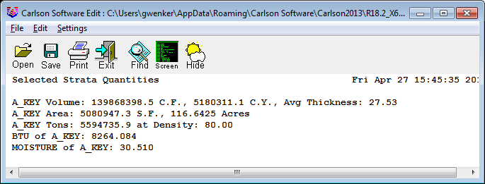
Entire Seam Composites In the first example, a body of ore has been sampled at 3 to 4 points vertically, as seen in the geologic columns. Note in the geologic columns (generated with Draw Geologic Column) that all the ORE has been assigned bed "A". This will "lump" the various ore samples into one "bed". If the bed name is not assigned when the holes are drawn, then this can be accomplished by the commands "Assign Bed Names" or "Fill in Bed Names". Then the command Selected Strata Quantities will produce this report (showing composite A tons) when the A_Key strata is chosen singly and the inclusion perimeter is selected. Compositing of the single A bed is automatic.
Note: The program will not composite qualities for a strata name
that is repeated, unless there is a bed name grouping them
together.
The command Selected Strata Quantities brings up
this screen to select the strata or bed to analyze.
Vertical Composite
Zones
In
the next example, a vertical zone of ore has been defined as the
upper part of the ore body or "A" bed from 4130 elevation and up.
The "floor" of the vertical cut in this case is flat, following the
4130 elevation. This might correspond to a mine plan where the base
of the first of two cuts is designed to hit elevation 4130 within
the entire pit. The technique required is to divide bed A into two
beds. This is done by the command "Split Bed" within
Strata/Bed Utilities under Drillhole. The prompting is as
follows:
Command: splitbed
Split strata method
[<Elevation>/Grid/Thickness]? E
Select the Drillholes for bed
split. Select the
holes
Select objects: Specify opposite
corner: 3 found
Enter name of the bed to
split: A
Rename bed or assign key/non-key
status [<Name>/Status]? Name
Enter new name for the upper part
of the bed: A
Upper
Enter new name for the lower part
of the bed: A
Lower
Enter a split elevation:
4130
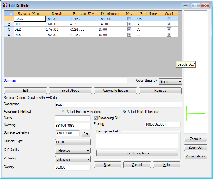
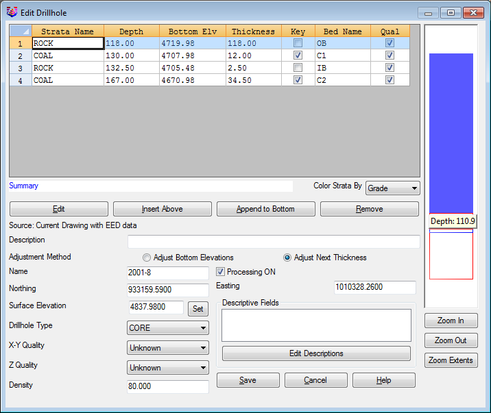
This shows a drillhole before splitting the A seam into an A Upper and A Lower.
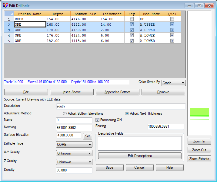 Here is
the same drillhole, viewed within "Edit Drillhole" after the
command "Split Bed". Notice the new Bed Names, A Upper and A
Lower.
Here is
the same drillhole, viewed within "Edit Drillhole" after the
command "Split Bed". Notice the new Bed Names, A Upper and A
Lower.
 The
result is a new base of A Upper seam. It is important to note that
the quality characteristics of the original ore zone have been
applied identically to the new ore zones that have been renamed to
A Upper and A Lower. The rest of the ore zone, the lower 12.5 feet,
has become part of A Lower. If a drillhole does not reach as low as
4130 elevation, then all the ore remains in the A Upper bed and is
unaffected. Conversely, if the ore never exceeds elevation 4130 in
a particular drillhole, then it is assigned bed A Lower for all the
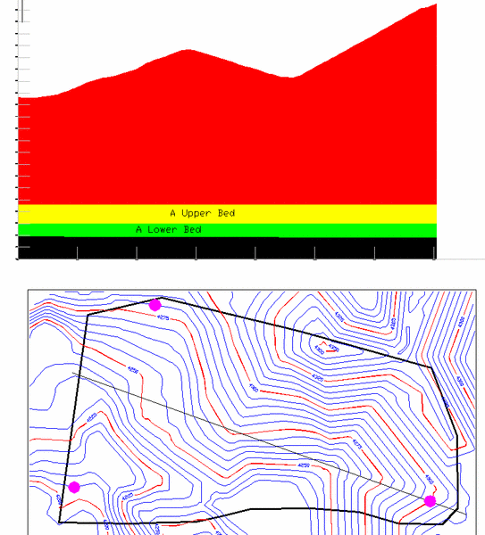
ore sample points. Here is a Fence Diagram showing the two
divisions of the bed, at elevation 4130.
The
result is a new base of A Upper seam. It is important to note that
the quality characteristics of the original ore zone have been
applied identically to the new ore zones that have been renamed to
A Upper and A Lower. The rest of the ore zone, the lower 12.5 feet,
has become part of A Lower. If a drillhole does not reach as low as
4130 elevation, then all the ore remains in the A Upper bed and is
unaffected. Conversely, if the ore never exceeds elevation 4130 in
a particular drillhole, then it is assigned bed A Lower for all the
ore sample points. Here is a Fence Diagram showing the two
divisions of the bed, at elevation 4130.
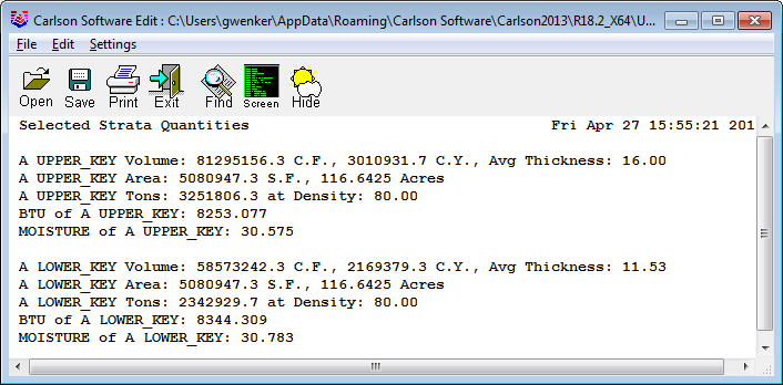
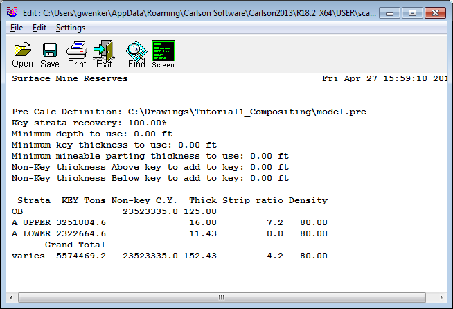
 Now the command "Selected Strata Quantities" can
be run. Ironically, you don't select the "composite" option because
you want to calculate the A Upper and the A Lower beds distinctly.
You select them one at a time from the dialog box. This leads to
the result shown here in the report. Adding the tons calculated
here: 3292460 + 2351700 = 5644160 calculated above, when the bed
was just A. This is a good check to make sure the quantities
match.
Now the command "Selected Strata Quantities" can
be run. Ironically, you don't select the "composite" option because
you want to calculate the A Upper and the A Lower beds distinctly.
You select them one at a time from the dialog box. This leads to
the result shown here in the report. Adding the tons calculated
here: 3292460 + 2351700 = 5644160 calculated above, when the bed
was just A. This is a good check to make sure the quantities
match.
 Split Bed by Grid
File
Split Bed by Grid
File
In the previous example, we chose to split the bed by elevation.
If, by contrast, the goal was to leave 5-feet of lower ore in place
to be removed by different equipment, then the vertical demarcation
is not a fixed elevation but a grid file defined as base of ore
plus 5 feet. This grid file is made by using "Make Strata Grid
Files" to make the base of ore, then using Grid File Utilities (in
the DTM or StrataCalc menu) you would add a value of 5-feet and
re-save the grid file as Oreplus5.grd or some such name. This new
file would be used to delineate the split elevation between the A
Upper and A Lower beds.
Advanced Mine Module
Techniques
In the above example, the command "Selected Strata Quantities" was
used. This is an "on-the-fly" selection approach, where the
drillholes are selected each time the command is run. It does not
take advantage of stored grid files in the Geologic Model file
(.PRE), which is the essence of the Advanced Mine Module. To apply
the above procedures to the Advanced Mine Module, follow this
sequence:
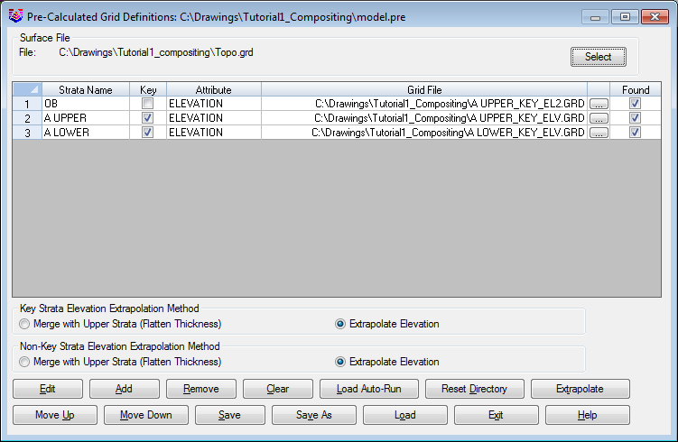
Then run Surface Mine Reserves, selecting Geologic Model as the
modeling method. You will obtain the same quantities for each bed
as reported from the command "Selected Strata Quantities".
The advantage of setting up grid files is that multiple, prenamed pits can be run within Surface Mine Reserves, and the reporting can be formatted and expanded upon at the user's discretion, even dumped to Excel and Access. The various options within Surface Mine Reserves can be fine-tuned, such as recovery percentage, density and dilution. Furthermore, "grand totals" are obtained where the qualities and volumes/tonnages of beds A Upper and Lower are composited back into the total reserve values. (Indeed, this is the exact procedure used for multiple seams with interburden.)
Shown here is a formatted report for the single inclusion
polygon representing the pit in our example. Slight differences in
values versus "Selected Strata Quantities" is a function of the
difference in gridding locations and cell sizes. With stored
Geologic Model grids, quantities and qualities will be fully
repeatable.

(2) Combinations of Several Seams Separated by Interburden
In the mining of stratified deposits it is very common to have several seams separated by interburden. Surface mines must consider the composite tonnage, composite strip ratio and composite quality in any reserve study or short-term mining plan. Two main issues come to mind—how deep to mine, and when to mine and remove interburden as if it were Key. Let's look at a coal deposit example.
How Deep to Surface Mine
Strip ratios change as each lower seam is taken, and quantities of
coal increase. The goal is to get as many lower seams as possible,
but not so many that interburden thicknesses and strip ratios
increase excessively, or quality degrades. Currently, about a 15:1
strip ratio approaches the maximum feasible ratio for
cost-effective mining. Higher ratios do occur and will certainly
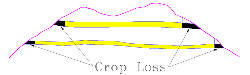
occur if the market price of coal increases. Coals are said to
"outcrop" at the surface, with "crop loss" referring to unmineable,
"weathered" coal at the hillside edge. Usually the crop loss is
around 12 to 15 feet measured vertically from the surface. It is
often deeper in valleys or even small hillside ravines and
"drains", due to accumulation of debris and erosion. On "points" or
ridges, crop loss may be only 10 to 12 feet, particularly in
hardrock conditions. The Surface Mine Reserves routine is designed
for estimating reserves and includes a built-in crop loss parameter
(measured vertically from the surface), appearing as "Min Depth to
Use". Here is a graphic representing the crop loss on the side of a
hill.
 A conservative engineer or geologist would enter
15 feet to obtain a "low-ball" estimate. Someone looking
aggressively for all the coal they could possibly obtain might
enter 10 or 12 feet for the vertical crop loss. Be aware that with
steep 1.5:1 hillside slopes, a 10' vertical crop loss translates to
15' measured horizontally from the hillside. In 3:1, gently sloping
terrain, a 10' vertical crop loss translates to 30' measured
horizontally from the hillside. If the natural terrain slopes on
the order to 2:1 to 3:1 or more, it is reasonable to use a lower
vertical crop loss value for "Min Depth to Use". The value used is
strictly a judgment call and is ideally based on observations at
the mine. There is no option to have a variable crop loss. That is
best handled by defining a "Strata Limit Polyline". See the
"OutCrops and SubCrops" case study. In many regions, shallow coals
will "subcrop" as they hit an alluvial deposit or as it nears the
surface and is decomposed due to oxidation and
weathering.
A conservative engineer or geologist would enter
15 feet to obtain a "low-ball" estimate. Someone looking
aggressively for all the coal they could possibly obtain might
enter 10 or 12 feet for the vertical crop loss. Be aware that with
steep 1.5:1 hillside slopes, a 10' vertical crop loss translates to
15' measured horizontally from the hillside. In 3:1, gently sloping
terrain, a 10' vertical crop loss translates to 30' measured
horizontally from the hillside. If the natural terrain slopes on
the order to 2:1 to 3:1 or more, it is reasonable to use a lower
vertical crop loss value for "Min Depth to Use". The value used is
strictly a judgment call and is ideally based on observations at
the mine. There is no option to have a variable crop loss. That is
best handled by defining a "Strata Limit Polyline". See the
"OutCrops and SubCrops" case study. In many regions, shallow coals
will "subcrop" as they hit an alluvial deposit or as it nears the
surface and is decomposed due to oxidation and
weathering.
Another Example: Getting Composite
Qualities
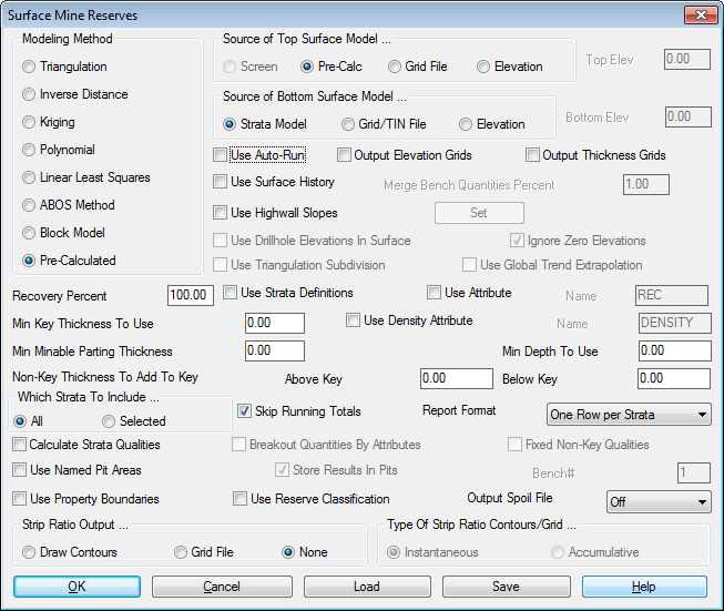
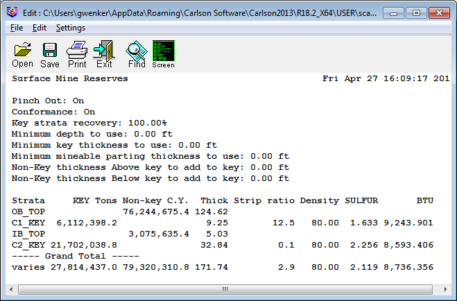
The Surface Mine Reserves command automatically computes composite
qualities and strip ratios on all Key strata, providing "Calculate
Strata Qualities" is selected in the dialog box (dialog shown
earlier above). The low SULFUR and BTU values for OB and IB are not
included in the composite quality for SULFUR and BTU. This is
because OB and IB are not defined as KEY. When C1 and C2 are
imported or placed in the drawing, they are defined as KEY strata.
Alternately, the KEY designation can be assigned and changed using
the command "Define Strata". Shown is a drillhole example of this
dataset, and the composite KEY quality report.
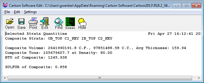
By contrast, composite qualities can also be computed using the
command "Selected Strata Quantities", but this routine will
composite any selected strata, key or non-key. In our example, if
all 4 beds are selected, the composite BTU is only 1245. All of the
above calculations were based on screen-selection of the drillholes
(not grid files), and use of Triangulation modeling. (Sulfur was
not entered for Nonkey beds). 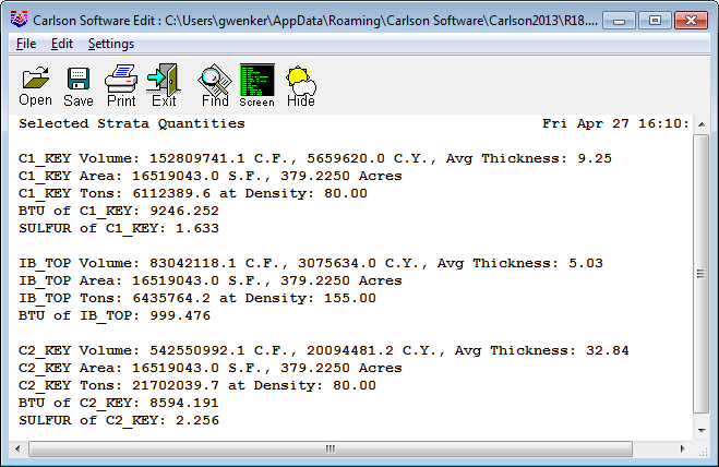
Partings: When to Mine and When to
Waste
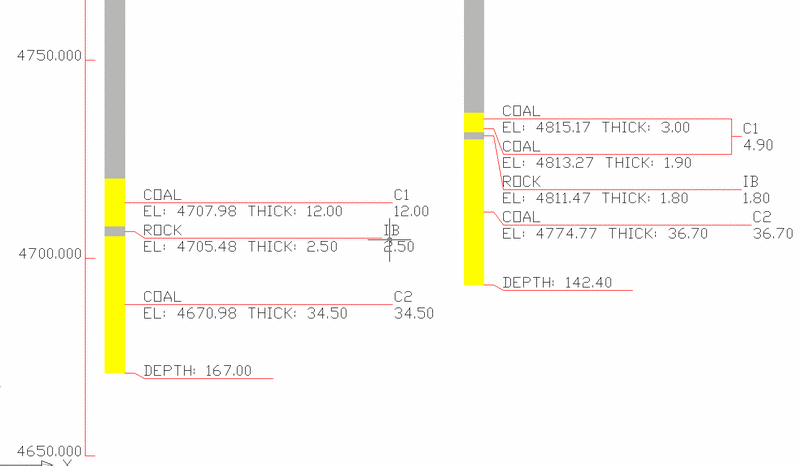
Drillholes 8 and 10 below have 2.5 and 1.8 feet of interburden,
respectively, between coals C1 and C2. It makes sense to take the
thin interburden with the coals, even though this will dilute some
qualities (and maybe improve others). Surface Mine Reserves has an
option called "Min Minable Parting Thickness" designed specifically
for this purpose. The effect on qualities is also shown below. This
result is obtained automatically by designating 2.0 feet as the
"minimum minable parting thickness", meaning that any lesser
thickness will not be separated as waste but will be included as
coal.
To obtain interburden qualities and to factor them in to the
composite quality, it was critical that qualities be associated
with non-key strata. This is accomplished within the command
"Define Drillhole" or a setting on the main Surface Mine Reserves
screen for Fixed NonKey Qualities.

In our example, the interburden had a density set at 150 within Define Strata, and had BTU values in the 1000 range, and sulfur in the 0.5 range. The net effect of including the thin interburden was to improve sulfur and degrade BTU. If sulfur under 1.0% is the more critical value in meeting quality requirements, and less BTU is satisfactory, then the user could accept thicker interburden. Compare these quality values with the ones calculated above and see how the SULFUR is lower and the BTU is also lower, but still within spec. Just try several reserve runs to see what the parting thickness cut off can be.