 Keyboard Command: BLKMODEL
Pull-down Menu Location: Block Model
Prerequisite: Drillholes with a bed name, and variable quality values that can be vertically modeled.
This is one of the initial commands to begin using
the block modeling features of Carlson. It uses similar grid logic,
for location and resolution in the X and Y. It will take bed and
subdivide it into vertical divisions. This can be applied to
stratafied deposits, or ore based geology, where it is not
stratafied, such as limestone or copper, gold and silver. In these
ore type cases, the strata or bed name could be just rock, or
limestone all the way down the hole. It would then look at just the
quality being modeled as the variable. The program takes this
interval, makes a roof and a floor and divides it up equally into
the number of vertical divisions specified, or at an elevation
"lift", where the top and bottom elevations are specified, and the
block height calculated based on the number of divisions.
The first dialog brings up the Select Bed and
Attribute screen. One bed name must be selected, and one or more
attributes selected. If there are no Bed names in the drillholes,
then select the Model By Strata Names box to use just Strata
names.


 The next screen, Make Block
Model, is for dimension and modeling settings. The number of cells
in the X and Y direction are shown at the top. The total number of
cells in plan view is shown next. The block height is determined by
the Number of Vertical Divisions and Vertical Position settings.
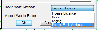
There are two options to determine the Vertical Position. The first
one is by Fixed Elevations. This will activate the Bottom Z and Top
Z windows where the roof and floor for the block model are entered.
The Follow Ore Model makes the top and bottom of the block model
follow the top and bottom elevations of the bed being processed.
The Use Fixed Elevations for Ore Model controls how the attributes
are interpolated for the Fixed Elevations mode. When this option is
on, the attributes are calculated at the fixed elevations. When
this option is off, the attributes are calculated within the
elevation range of the bed and then interpolated to fit within the
fixed elevations. The Number of Vertical Divisions controls the
number of block model data points between the top and bottom of the
block model.
The next screen, Make Block
Model, is for dimension and modeling settings. The number of cells
in the X and Y direction are shown at the top. The total number of
cells in plan view is shown next. The block height is determined by
the Number of Vertical Divisions and Vertical Position settings.
There are two options to determine the Vertical Position. The first
one is by Fixed Elevations. This will activate the Bottom Z and Top
Z windows where the roof and floor for the block model are entered.
The Follow Ore Model makes the top and bottom of the block model
follow the top and bottom elevations of the bed being processed.
The Use Fixed Elevations for Ore Model controls how the attributes
are interpolated for the Fixed Elevations mode. When this option is
on, the attributes are calculated at the fixed elevations. When
this option is off, the attributes are calculated within the
elevation range of the bed and then interpolated to fit within the
fixed elevations. The Number of Vertical Divisions controls the
number of block model data points between the top and bottom of the
block model.Discrete is a method to model parameters such as
color. It will carry one color 1/2 way over to the next drillhole,
then switch to the other color. This way, there is now blending of
colors, if color1 is a 2 in one drillhole and color2 is a 4 in the
next drillhole, it will not blend them to a "3" in the middle. It
models 2, and then switches to 4 at the halfway point.
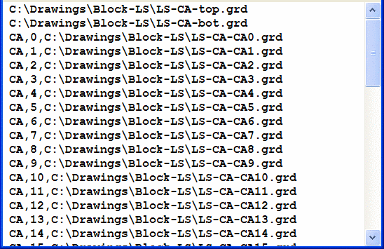
After the routine is finished calculating, it creates a *.BLK file. This file can be viewed in a text editor to see what it contains, as shown here. Basically, it shows the roof and floor, the quality attribute name and the file paths of each level of the block qualities.
Keyboard Command: BLKMODEL
Pull-down Menu Location: Block Model
Prerequisite: Drillholes with a bed name, and variable
quality values that can be vertically modeled.