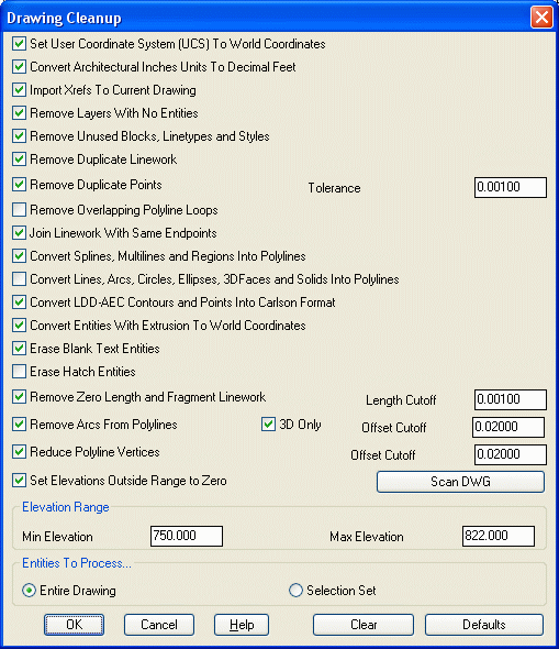
The Drawing Cleanup dialog box allows you to
perform many functions that fix common errors, and it removes
unnecessary data found in many drawing files. It also converts
incompatible data into useful entities. This command offers many
filters that audit the drawing file and allows you to select which
options and settings you want to use. A report of the cleanup
results will be displayed upon completion. Always save your file
when the drawing cleanup routine is complete.
Set UCS to World
Coordinates
This sets the UCS (user coordinate system) to the world coordinate
system (WCS). Carlson works exclusively in the world
coordinate system and there is no way to change this setting. In
CAD, it is possible to change the coordinate system from WCS. If
you receive a drawing in which the coordinate system is not set to
world, click this on to restore the UCS.
Convert Architectural Inches Units To Decimal Feet
Drawings are sometimes in architectural units, i.e. inches, when the unit of measurement was intended to be in feet. This routine will change the units from inches into feet and then scale the drawing by 1/12.
Import Xrefs To Current Drawing
This routine allows you to import any 'found' external reference files (Xrefs) into the current drawing. If the path is not found, the Xref file will not be brought into the drawing. To set the Path for any unfound Xrefs, run Import Xref to Current Drawing under File.
Remove Layers With
No Entities
Drawings work with a "BYLAYER" concept meaning that layer
definitions define the drawing. For example, the layer named EOP
might be used to display polylines at the Edge Of Pavement in the
drawing. Many times extra layers get defined by a user but not used
to display any objects. This function removes any layers defined in
the drawing that are not being used.
Rename Layers With
Wildcards
Layers with wildcard characters such as "*" can interfere with
Carlson layer matching functions. This routine renames layers by
replacing any wildcard characters with an underscore "_".
Remove Unused
Blocks, Linetypes and Styles
This functions removes
this unused information from the drawing.
Remove Zero Length
Linework
This function seeks out and removes any linework definition that
have zero length. Point nodes are not removed.
Remove Duplicate
Linework
This function finds any duplicate linework in the drawing and
removes all but one set.
Remove
Duplicate Points
This function searches the drawing
(but not the .CRD file) for points with the same northing, easting
and elevation. The tolerances for considering points to have the
same coordinate are set to the right. To be counted the same
coordinate, both the northing/easting and elevation must be within
the tolerance distance.
Remove Overlapping Polyline
Loops
Polylines that completely overlap themselves are broken into two
different polylines.
Join Linework With Same
Endpoint
This function finds common endpoints on linework on common layers
with common elevations and joins the linework into a continuous
polylines. This is very helpful for future selection sets.
Convert Splines, Multilines and
Regions Into Polylines
Some CAD applications utilize Spline Object Definitions and
Regions, Carlson utilizes basic polyline/polygon definitions. This
function finds any Splines and/or Regions defined in the drawing
and re-defines them as simple polylines or polygons.
Convert Lines, Arcs, Circles,
Ellipses, 3DFaces and Solids Into Polylines
By converting Lines, Arcs, Circles, Ellipses, 3D Faces, and Solids
into Polylines, you can use the variety of Polyline commands
available in Carlson.
Convert LDD-AEC Contours and
Points Into Carlson Format
Drawings created in the Land Development Desktop CAD program can
contain special objects known as LDD-AEC contours that define their
topographic contour display. This function locates those special
objects and re-defines them as simple 2D polylines retaining
their elevation values.
Convert Entities With Extrusion To World Coordinates
Drawings created in the Land Development Desktop CAD program can
contain special objects known as LDD-AEC contours that define their
topographic contour display. This function locates those special
objects and re-defines them as simple 2D polylines retaining their
elevation values.
Erase Blank Text
Entities
This function removes any text boxes defined in the drawing that
are not being used.
Erase Hatch
Entities
Carlson offers many hatch display options, however hatch entities
have no 3D value. This function removes all hatch entities in the
original drawing to help reduce the size and clutter of the drawing
file.
Remove Arcs From Polylines -
Offset Cutoff
This function replaces arcs in polylines with a series of short
chord segments. The purpose is to prepare the polylines for
modeling since arcs need to be converted into segments to be part
of the triangulation model. The density of chord segments is
controlled by the offset cutoff. This cutoff represents how much
the polyline can move horizontally. A smaller cutoff will result in
more chord segments. The option for 3D Only controls whether only
polylines at zero elevation or both zero and elevated polylines get
processed. Sometimes you may want to leave the arcs in zero
elevation polylines when these polylines represent road alignments
and are not part of the surface model.
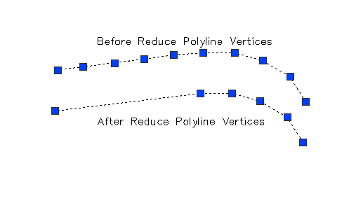
Reduce Polyline Vertices -
Offset Cutoff
This function utilizes a pre determined offset amount and removes
unnecessary polyline vertices that fall within the offset
amount.
Set Negative Polyline Thickness to
Zero
This function sets the thickness property
of polylines to zero for polylines with negative
thickness.
Set Elevations Outside Range to Zero and Elevation
Range
This function comes with a "Scan DWG" option that audits the
elevation range in the drawing file. Once the minimum and maximum
elevation range has been set, manually or by a scan, all objects
that fall outside the set range are moved to elevation zero. All
objects at zero elevation do not contribute to the 3D model.
Entities To
Process...
This allows you to run the command for the entire drawing or for a
selected set.
Default
This allows you to return to the Carlson Drawing Cleanup default
settings.
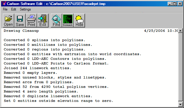
Final Report
This example report displays the results of drawing cleanup. Like
all reports in Carlson, this report can be saved to a text file,
sent directly to your printer, or pasted onto the screen ad text
entities.
Pulldown Menu Location: File
Keyboard Command: dwg_cleanup
Prerequisite: None