Best Practices for Inserting New Items to Standards
Database
Once Standard Items have been defined to your Standards Database,
many properties of those Items cannot be modified. For instance, if
you have defined an Annotation entity having a Left justification
to your database and later realize it should have Center
justification, it cannot be changed. To correct it, you must first
delete the Standard Item from the database, create a Text entity
with the correct justification and then re-Insert the Item to the
database.
Therefore, it is recommended that you create a "Source Drawing" to
help you plan, set up and define the Standard Items to be added to
your Standards Database.
Source Drawing
The Source Drawing should contain small clusters of entities
organized according to the Standard Items to be defined. For each
Standard Item to be defined, all of the Symbol, Linework and
Annotation entities comprising that Item should be drawn or
inserted into the Source Drawing.
The Symbols, Linework and Annotation entities used to define
Standard Items should be drawn at 1:1 and should have Color and
Linetype set to "ByLayer". These entities should reside on their
standard layers and be drawn with the appropriate text styles, text
heights, text justification, linetypes and dimension styles. Only
one type of Standard entity can be defined for a Standard Item. For
instance, only one Symbol can be defined per Standard Item.
Before drawing or inserting the components of the Standard Items
into the Source Drawing, set the "Horizontal Scale" in
Carlson Drawing Setup to 1:1. This ensures that
new "Horizontal Scale" settings will be applied correctly when
these Standard Items are drawn into new drawings.
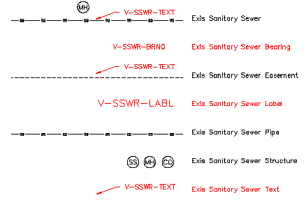
A representative sample of a Source Drawing is shown below. A few
notes:
- A new Item named "Exis Sanitary Sewer" will be created and will
have a Symbol, Linework and Annotation component. The Symbol
resides on layer V-SSWR-STRC. The Linework resides on layer
V-SSWR-PIPE. The Text and Leader reside on layer V-SSWR-TEXT.
Text/MText entities and their associated Leaders are considered ONE
Annotation entity when defining to the standards database.
- Notice that the Symbol does not have to be positioned at the
endpoint of the Linework when defining as Standard Items. The
Symbol will automatically be placed at each vertex of the Linework
when it's drawn into the drawing.
- All Text except for that on layer V-SSWR-LABL is drawn with a
height of 0.08 and is Left justified. The Text on layer V-SSWR-LABL
has a height of 0.12 and is Center justified.
- There are 3 different Symbols to be defined as Items to the
database. One may be named, "Exis Manhole", another "Exis Cleanout"
and the other "Exis SS Manhole". All 3 Symbols reside on layer
V-SSWR-STRC. Note that the same block, the "MH" Symbol, will be
defined to the database twice as a component of two different
Standard Items - "Exis Sanitary Sewer" and "Exis Manhole".
Tips for Inserting Standard Symbol Items
When being defined, Symbol entities should be drawn at 1:1 (plotted
text height).
The Layer of the Symbol entities will be defined to the Standards
database; however, because the Color and Linetype of the Symbol
were defined as "ByLayer", when placed into a new drawing on the
defined layer, the new Symbol Item will follow the Color and
Linetype settings of that layer in the new drawing.
Symbols can be defined with or without a Leader.
Symbols and their associated Leaders are considered ONE Annotation
entity when defining to the standards database.
Make sure to use the QLEADER command to ensure
Symbol and Leader associativity.
The Dim Style of the QLEADER entity will be
defined to the Standards database.
Standard Symbol components can be defined having a "Fixed" size or
the size can be scaled according to the "Horizontal Scale" of the
drawing.
If Symbol components are drawn and scaled according to the
"Horizontal Scale", the "Horizontal Scale" setting is saved with
the entity. In other words, changes to the "Horizontal Scale" of
the drawing will not affect existing entities. This is true of
Symbols and Leader components.
When defining Symbols/Blocks, it is helpful to include a
WIPEOUT entity behind the Symbol so that
underlying Linework is hidden without changing its geometry.
Symbol/Block definitions can contain Text and/or Attributes.
When creating a Standard Symbol Item containing Attributes, you can
select the options for "Allow Move" and "Allow Rotate" to easily
move and rotate each Attribute independently of the other block
entities.
Using Attributes inside of Symbol/Block definitions allows for
additional data storage in each block. For instance, when
Attributes are used, data that is valuable to a GIS can be stored
with each Block/Symbol.
When defining Attributes inside Symbol/Block definitions, set the
"Constant" flag to keep the Default Value for the Attribute. If the
"Constant" flag is not set, you will be prompted for a new
Attribute Value each time the Symbol is inserted.
When defining Attributes inside Symbol/Block definitions, use the
pipe symbol "|" to provide a drop-down box with optional Attribute
Values. For instance, a Sanitary Sewer Structure may have a label
defined by an Attribute having Default Value, "MH|CO|SS". Note that
this does not work if the "Constant" flag is set for the
attribute. Upon insertion, you
are given a dialog prompting you to Define Attribute
Values by selecting from the available options:
Upon insertion, you
are given a dialog prompting you to Define Attribute
Values by selecting from the available options: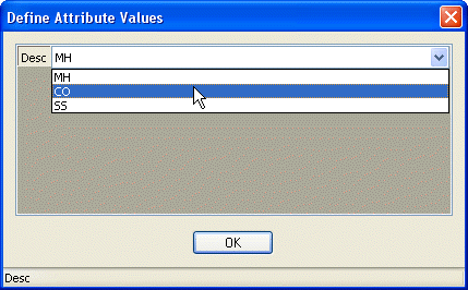
Tips for Inserting Standard Linework Items
The Layer of the Linework entities will be defined to the Standards
database; however, because the Color and Linetype of the Linework
entities were defined as "ByLayer", when placed into a new drawing
on the defined layer, the new Linework Item will follow the Color
and Linetype settings of that layer in the new drawing.
To manage Linetype Scale using the LTSCALE
command, the Scale value of "1" must be set to "Fixed" during the
Insert
Item or Modify
Item commands.
Using the Offset option,
you have the ability to draw multiple Linework Items parallel to
one another.
Tips for Inserting Standard Annotation Items
Annotation elements may be defined using DTEXT or
MTEXT commands but will always be placed as
MTEXT entities in the drawing.
When being defined, Text or MText entities should be drawn at 1:1
(plotted text height).
The Text Style, Height and Justification of the Text or MText
entities will be defined to the Standards database.
The Layer of the Text or MText entities will be defined to the
Standards database; however, because the Color and Linetype of the
Annotation were defined as "ByLayer", when placed into a new
drawing on the defined layer, the new Annotation Item will follow
the Color and Linetype settings of that layer in the new
drawing.
Annotation elements may be defined with Leaders or without.
Text/MText entities and their associated Leaders are considered ONE
Annotation entity when defining to the standards database.
Make sure to use the QLEADER command to ensure
Annotation and Leader associativity.
The Dim Style of the QLEADER entity will be
defined to the Standards database.
Standard Annotation components can be defined having a "Fixed"
Height or the Height can be scaled according to the "Horizontal
Scale" of the drawing.
If Annotation components are drawn and scaled according to the
"Horizontal Scale", the "Horizontal Scale" setting is saved with
the entity. In other words, changes to the "Horizontal Scale" of
the drawing will not affect existing entities. This is true of Text
and Leader components