Item Standards Manager
The Item Standards Manager command launches the
Standards Draw Manager palette. This palette has a
right-click shortcut menu allowing you to Insert, Modify, Delete
and otherwise manage Items stored in the Standards Database file
(.sdb). Other than the shortcut menu, this palette is identical to
the Standards Draw palette.
The first time you launch the Item Standards
Manager in a drawing session, a dialog box will prompt you
to "Select Drawing Standards Data
Source".
The Standards Data Source can be loaded by specifying a Universal
Data Link file (.udl) or a Standards Database file (.sdb). The .udl
file is a file that "points" to an .sdb file. CAD Managers may
prefer to allow users access to the database through the Universal
Data Link file (.udl). This allows the CAD Manager to limit access
to the Standards Database file (.sdb) by storing it in a non-shared
location. The CAD Manager can set "read only" or "read/write"
permissions for the .udl file so as to limit editing access to the
protected data stored in the .sdb file.
Carlson includes two Standards Database files (.sdb) with the
installation: the
Carlson_NCS_SurveyCivil.sdb which is a
fully populated database based on the US National CAD
Standard and empty.sdb which is
a functional, but empty, database with which to start a new
Standard Database. Updates and additions to the .sdb files provided
by Carlson Software will be posted to this website:
www.carlsonsw.com/cadstandards.html.
After specifying the data source, the CAD Standards feature is
launched in "CAD Management" mode and the Draw Standard
Item command is automatically issued. If you wish to place
a Standard Item in your drawing at this time, you can simply
continue the Draw Standard Item command as usual.
However, if you need to perform any management tasks to the
database, use the Enter key to finish the command
and return to the Command: prompt. You can then access the
Standards Draw Manager palette by hovering over
the Draw Standard Item icon on the
Draw Item toolbar.
By default, the Standards Draw Manager palette
automatically hides within the Draw Standard Item
icon. Hovering over this icon will display the palette. Once
displayed, the palette may be dragged to a new location and
re-sized. Since the palette is fully transparent, it can be
"parked" in the drawing area and not interfere with other drafting
tasks. The palette is also "transparent" with regards to command
execution in that other commands are able to run while the palette
remains open and available for use.
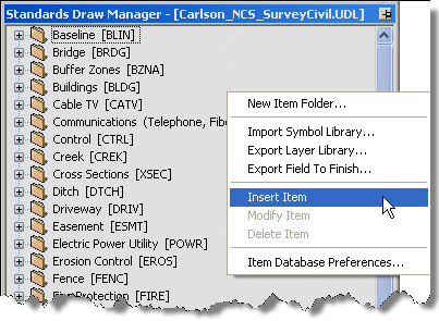 Once displayed,
right-clicking inside the Standards Draw Manager
displays a menu containing the Standards Database management
commands.
Once displayed,
right-clicking inside the Standards Draw Manager
displays a menu containing the Standards Database management
commands.
New Item Folder
Use this command to create a new folder or sub-folder in which to
store Standard Items.
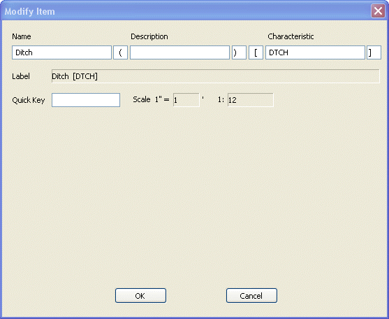 Name: The
common name for Items in this Folder. The Folder Name is limited to
32 characters.
Name: The
common name for Items in this Folder. The Folder Name is limited to
32 characters.
Description:
Additional descriptive information about this
Folder. The Folder Description is limited to 32
characters.
Characteristic:
Distinguishing characteristic of this Folder.
The Folder Characteristic is limited to 32 characters.
The "Name", "Description" and "Characteristic" of each new Folder
can be organized and named using any consistent naming convention
that makes sense for your office. The dialog also allows you to
specify a "Prefix" and "Suffix" for both the "Description" and
"Characteristic" of each new Folder. The "Prefix" and "Suffix"
values shown in the example above have been set as parentheses ( )
and brackets [ ]. You can set the Default values for "Prefix" and
"Suffix" in Item Database
Preferences.
Label: This is a read-only value defined by combining the Folder
Name, Description and Characteristic.
Quick Key:
This value is not used or set for
Folders.
Scale: This read-only value displays the current "Horizontal
Scale" as specified in Carlson Drawing
Setup.
Import Symbol Library
This command allows you to import a collection of blocks into the
database as Standard Symbol Items. Default Scale, Attribute
Properties and Rotation can be set for all symbols when importing
to the database. For this command, all blocks should be saved out
to individual Drawing files (.dwg) in a common blocks folder. And,
contrary to accepted CAD practice, the blocks should be drawn on
their standard layer instead of layer 0.
For instance, according to our standard, symbol SSWR-08 should
reside on layer V-SSWR-STRC. If I intend to import this symbol into
the database using the Import Symbol Library
command, the symbol SSWR-08 should reside in its own drawing file
named SSWR-08.dwg and should be drawn on layer V-SSWR-STRC in that
Drawing file.
Except as noted above with regard to layers, all Symbols should be
drawn according to the guidelines set forth in the Best Practices
section of this document.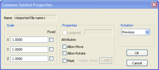 Scale: Because the default X, Y
and Z scale factors correspond to the current "Horizontal Scale"
setting in Carlson Drawing Setup, these values
should all be set to "1" when defining Standard Symbol Items to the
database.
Scale: Because the default X, Y
and Z scale factors correspond to the current "Horizontal Scale"
setting in Carlson Drawing Setup, these values
should all be set to "1" when defining Standard Symbol Items to the
database.
Select the "Fixed" options for X, Y and Z
Scales if you wish to manage the Symbol size solely by these
values. Do NOT select the "Fixed" options if you want the Symbol
size to vary depending on the "Horizontal Scale" setting of the
drawing.
Properties:
For blocks having defined attributes, use the
settings here to Allow Moving, Rotating and Masking of
attributes.
Rotation:
Default Rotation for Symbols can be specified
as "First", "Fixed" and "Previous". The "First" option will prompt
for a Rotation angle for the first Symbol and then will
automatically Rotate all subsequent Symbols to the same angle as
the first. The "Fixed" option will use the Rotation angle as
specified for the original Symbol. The "Previous" option will
prompt for the Rotation angle of each Symbol that is placed, but
will default to the Rotation angle of the previously placed
Symbol.
Browse for Folder:
Browse to and select the folder containing the
Symbols to be imported. After importing Symbols from a folder, the
database will automatically add the folder to the list of
"Additional Support Paths" as specified in the Item Database Preferences.
In order to insert the Symbol into other drawings in the future,
the source drawing file containing the original Symbol/Block
definition must be found in a Support Path.
Export Layer Library
Use this command to export all layers and associated properties
(color, linetype, etc.) to a Layer Library file (.la).
Export Field to Finish
Use this command to export all Standard Items to corresponding
field codes in a Field to Finish file (.fld).
Insert Item
Use this command to define a Standard Item to the Standards
Database file (.sdb). If you wish to store the new Standard Item in
a Folder, you must first select and highlight the Folder, then
right-click and select Insert Item from the
shortcut menu. If you do not want the new Standard Item saved in a
Folder, simply right-click anywhere in the palette and select
Insert Item. Once Items have been created, you can
simply "drag and drop" Items from one Folder to another as
needed.
A Standard Item, when defined to the database, can include any one
or a combination of 3 types of entities: Symbols, Linework and Annotation (with or without a Leader). If
more than one of any type (2 Symbols, for instance) are selected,
you will be prompted to select the ONE entity to be used for the
Standard Item definition.
Prior to Inserting a new Standard Item, all entities should be
drawn according to the guidelines set forth in the Best Practices
section of this document.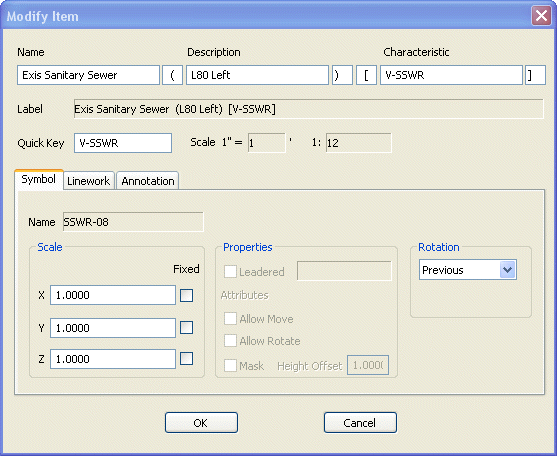 Select Objects: Select the entities that comprise the new Standard Item to
be defined.
Select Objects: Select the entities that comprise the new Standard Item to
be defined.
Name: The common name for this Item. The Item Name is limited to
32 characters.
Description:
Additional descriptive information about this
Item. The Item Description is limited to 32 characters.
Characteristic:
Distinguishing characteristic of this Item.
The Item Characteristic is limited to 32 characters.
The "Name", "Description" and "Characteristic" of each new Item can
be organized and named using any consistent naming convention that
makes sense for your office. The dialog also allows you to specify
a "Prefix" and "Suffix" for both the "Description" and
"Characteristic" of each new Item. The "Prefix" and "Suffix" values
shown in the example above have been set as parentheses ( ) and
brackets [ ]. You can set the Default values for "Prefix" and
"Suffix" in Item Database
Preferences.
Label: This is a read-only value defined by combining the Item
Name, Description and Characteristic.
Quick Key:
This is a nickname for the Standard Item. The
Quick Key is used with the Draw Item command and
allows you to specify the Standard Item to be drawn from the
Command: line.
Scale: This read-only value displays the current "Horizontal
Scale" as specified in Carlson Drawing
Setup.
Symbol tab
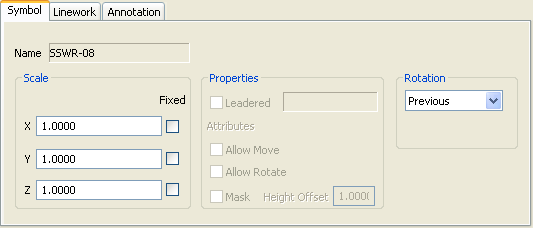 Scale: Because the default X, Y
and Z scale factors correspond to the current "Horizontal Scale"
setting in Carlson Drawing Setup, these values
should be set to "1" when defining Standard Symbols to the
database.
Scale: Because the default X, Y
and Z scale factors correspond to the current "Horizontal Scale"
setting in Carlson Drawing Setup, these values
should be set to "1" when defining Standard Symbols to the
database.
Select the "Fixed" options for X, Y and Z
Scales if you wish to manage the Symbol Size solely by these
values. Do NOT select the "Fixed" options if you want the Symbol
Size to vary depending on the "Horizontal Scale" setting of the
drawing.
Properties:
For blocks having defined attributes, use the
settings here to allow Moving, Rotating and Masking of
attributes.
Rotation:
Default Rotation for Symbols can be specified
as "First", "Fixed" and "Previous". The "First" option will prompt
for a Rotation angle for the first Symbol and then will
automatically Rotate all subsequent Symbols to the same angle as
the first. The "Fixed" option will use the Rotation angle as
specified for the original Symbol. The "Previous" option will
prompt for the Rotation angle of each Symbol that is placed, but
will default to the Rotation angle of the previously placed
Symbol.
Linework tab
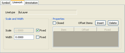 Linetype: This read-only value reflects the Linetype of the Linework
element. Using a "ByLayer" value allows for maximum flexibility in
the future.
Linetype: This read-only value reflects the Linetype of the Linework
element. Using a "ByLayer" value allows for maximum flexibility in
the future.
Scale and Width:
The Scale and Width settings shown here
reflect the Linetype Scale and Width of the entity selected. These
values can be modified and can also be specified as "Fixed".
Select the "Fixed" option for "Scale" if you wish to manage the
Linetype Scale of the entity solely by this value. Do NOT select
the "Fixed" option if you want the drawing's LTSCALE setting to
control the Linetype Scale of each entity.
Note: The "Fixed" option here applies to the
Current Entity Linetype Scale and not the global LTSCALE
that we are accustomed to changing based on the scale of the
drawing. For the LTSCALE to behave in its traditional fashion, it
requires the Current Entity Linetype Scale value be set
"Fixed" to "1".
Select the "Fixed" option for "Width" if you wish to manage the
Width of the entity solely by this value. Do NOT select the "Fixed"
option if you want the Width of the linework to be scaled by the
"Horizontal Scale" of the drawing.
Closed:
Select this option if the Linework is to be
forced to be a "Closed" polygon.
Offset Items - Insert:
This button can be used to draw multiple
Linework Items parallel to one another. When defining Offsets, you
will Insert one Linework Item to the database and then specify the
other Linework Items to be drawn parallel to the original Item. The
Offset Linework Items do not have to be drawn at the correct
Offset. After each Offset Item has been selected, you will be
prompted to specify the Offset distance from the original
Item.
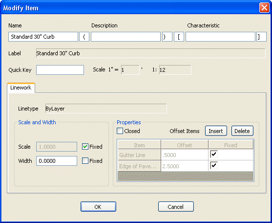
For instance, in addition to defining separate Standard Items for
"Back of Curb", "Gutter Line" and "Edge of Pavement", you might
also define a Standard Item named "Standard 30" Curb" that combines
all three Standard Items.
First, use the Insert Item command and select the
"Back of Curb" Item as the first Item.
Next, pick the Offset button and select a "Gutter Line" Item that
has been previously drawn in the drawing. You'll be prompted at the
Command: Line to specify the Offset Distance from the original
Item. This value can also be added or changed in the dialog box.
The Offset Distance for the "Gutter Line" would be 0.5,
representing a 0.5' wide curb.
Next, pick the Offset button again and select an "Edge of Pavement"
Item that has been previously drawn in the drawing. Again, you'll
be prompted at the Command: Line to specify the Offset Distance
from the original Item. The Offset Distance for the "Edge of
Pavement" would be 2.5, representing a 2.5' wide curb with
gutter.
After being added as Offsets, both of these values should be marked
as "Fixed" because their Offset values should not change based on
the "Horizontal Scale" of the drawing.
Offset Items -
Delete: After selecting an
Offset, pick this button to delete the Offset from the Standard
Item.
Annotation tab
 Style: This
read-only value reflects the Text Style of the Annotation
element.
Style: This
read-only value reflects the Text Style of the Annotation
element.
Height and Width
Factor: The Height and Width
Factor settings shown here reflect the Text Height and Width Factor
of the entity selected. While both the Height and Width Factor can
be modified, the Width of the text is a read-only, computed value.
You also have the option of specifying the Height as "Fixed".
Select the "Fixed" option for "Height" if you wish to manage the
Height of the entity solely by this value. Do NOT select the
"Fixed" option if you want the Height to vary depending on the
"Horizontal Scale" setting of the drawing.
Rotation:
Default Rotation for Annotation can be
specified as "First", "Fixed" and "Previous". The "First" option
will prompt for a Rotation angle for the first Annotation entity
and then will automatically Rotate all subsequent entities to the
same angle as the first. The "Fixed" option will use the Rotation
angle as specified for the original Annotation entity. The
"Previous" option will prompt for the Rotation angle of each
Annotation entity that is placed, but will default to the Rotation
angle of the previously placed entity.
Leadered:
Select this option if you wish to have the
ability to place a Leader with each instance of your Annotation.
The Leader option is only available if you selected both a
Text/MText entity and a Leader entity when Inserting the Item to
the database. The read-only value to the right reflects the
Dimension Style of the Leader entity selected.
Mask: Select this option if you wish to have each instance of
Annotation "masked" using a WIPEOUT entity. If
selected, the "Height Offset" option becomes active allowing you to
control the size of the WIPEOUT.
Modify Item
Right-click on any Item or Item Folder and select Modify
Item to make changes.
Delete Item
Right-click on any Item or Item Folder and select Delete
Item to remove the Item from the database.
Item Database Preferences
Right-click in the palette and select this command to manage Item
Description and Characteristic Prefix and Suffix values and also to
Add or Delete "Additional Support Paths".
Keyboard
Command: configItem
Prerequisite:
Populated Standards Database file
(.sdb)