|
|
From the Field to Finish routine |

This command allows you to locate symbols using multiple insertion points. Up to three insertion points can be defined for an individual symbol. When defining only two insertion points for a particular symbol, the symbol will be scaled and rotated. With three insertion points defined, the symbol is rotated and scaled in both the X and Y directions. The two point insertion definition will aid in the drawing of tree symbols with a specific drip line width. For instance, a surveyor could locate the tree and then locate the drip line, two shots for each tree, and allow the program to size the tree symbol accordingly so that the map will have various tree symbol sizes that reflect the actual field conditions.
The multiple insertion points are defined in the Field to Finish codes. The Insert Multi-Point Symbols command reads the Field to Finish code table and finds all of the codes with multi-point symbol definitions. Then you can select from these codes for the symbol to draw. Both the two and three point insertion definitions can aid with the insertion of concretes and buildings symbols during final drawing preparations and design phases of a project.
Here are the various steps to define two point and three point insertion point symbols. First, you must decide on the symbol to use for the desired code, as well as the specific placement points for the symbol. Once a symbol has been chosen, open the desired symbol drawing. To do this, identify the symbol name and then locate the symbol by its drawing name under the SUP sub-directory found under the Carlson installation directory. Next, determine the placement points for the symbol. As shown below, the placement points for the BLD code symbol, which will be explored later in this section, were determined by identifying X and Y values of the desired placement points by using the id command and specifying the end points of the lines.
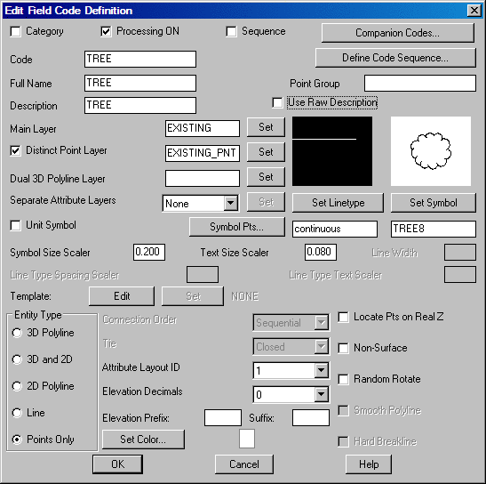
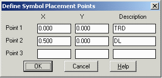
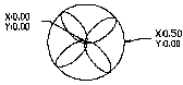
Next, the symbol insertion points must be defined in the Field to Finish code table (.FLD) file. To do this, open your FLD file by choosing Draw Field to Finish under the Survey pulldown. Then select a particular code from the list of codes displayed in the Field to Finish dialog box. Edit it by highlighting the code and picking the Edit button, or define a new code with the Add button. Either choice will display the Edit Field Code Definition dialog. In the Edit Code Definition dialog, choose the desired symbol for the code by pressing the Set Symbol button and selecting the desired symbol. Next, select the Symbol Pts button. This brings up a dialog called Define Symbol Placement Points. Here is where you define the symbol by three points. You do this by entering an X and Y coordinate and a description for the symbol. Enter the X and Y values for each placement point into the appropriate fields. The description fields are used as the prompts when placing the symbol in the drawing. A two insertion point symbol is defined in the same way. An example is the Symbol Pnts definition for the code TREE. The placement points for the Tree code symbol were determined by opening the symbol drawing and finding the X and Y values at the insertion points. The center of the large circle was chosen for Point 1 and the East Quadrant was chosen for point 2. In both cases osnaps were used in picking the points.
Now that we have the codes defined, let's go through the Insert Multi-Point Symbol command and see the results. The command starts with a dialog that lists all the codes with Multi-Point Symbols defined. At this point you can select the symbol to draw. The symbol size applies only to using one point to place the symbol. When two or more points are used, the symbol is scaled to fit the points. Let's look at the BLD code three point insertion definition. Shown below are three points that represent a building pad. We want the building to be exactly the same dimensions defined by the point locations.
The three point PAD and the tree with drip line examples follow.
We start by specifying the building pad codes.
Insert Multi-Point Symbol Dialog
Choose a symbol to draw. In this example, the Pad symbol is a 3
point multi-symbol.
Specify LTFNT PAD point.
Pick Point or Point Number (Enter to End): 15
Specify LT REAR PAD point.
Pick Point or Point Number
(Enter to End): 16
Specify RT REAR PAD point.
Pick Point or Point Number (Enter to End): 17
Insert another BLD symbol [<Yes>/No]? N
Insert Multi-Point Symbol Dialog
Choose a symbol to
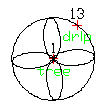
draw. In this next example, the Tree symbol is a 2 point
multi-symbol. Now specify the location of the trunk and the drip
line by point number.
Specify Trunk Location point.
Pick Point or Point Number (Enter to End): 1
Specify Drip Line Point.
Pick Point or Point Number (Enter to End): 13
Insert another TREE symbol [<Yes>/No]?
N
|
|
|
From the Field to Finish routine |
|
| Two points symbol placement for TREE |

|
| Three points for building PAD |
|
| Two point tree with drip line |
Pulldown Menu Location: Draw > Symbols
Keyboard Command: multsym
Prerequisite: Field to Finish file (.FLD) with codes defined
with Multi-Point Symbols