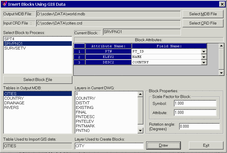
This command draws block entities in the drawing with the attributes filled out using data from a database. The command works through the dialog shown. The MDB File is the database that to be used as the source for the attribute data. The CRD File is the coordinate file that contains point number, northing, easting, elevation, and description. A list of the block definitions found in the drawing is shown on the left. To add a block to this list, pick the Select Block File. Highlight a block name from this list. Then the program will display a list of the block attributes. The tables defined in the current MDB database are listed in the lower left of the dialog. Highlight a table name to use for the data source. Then in the attribute list, for each block attribute you can set the database field to use for the attribute value by selecting the Field Name pulldown arrow. In the lower right of the dialog, you can specify the layer name, scale factors and rotation for the blocks.
Pick the Draw button to create the blocks. For each point number
in the coordinate file, the program will insert the specified block
in the drawing using the point coordinates from the CRD file. The
database record to use is found by matching the point number from
the coordinate file with the PT_ID field in the database
table.
Pulldown Menu Location: GIS Data
Keyboard Command: insert_blk
Prerequisite: CRD file and MDB database table file