Reduce Traverse
The Reduce Traverse feature allows you to reduce a raw data file,
with or without adjustment, and thus create a coordinate file or
append to an existing coordinate file.
NOTE: Before you
reduce a traverse, check the traverse settings on the Traverse
Options tab of the C&G Options dialog.
Select the type of adjustment to
use: (Compass, Least Squares, etc..)
Adjust Angles: (off/on)
Balance Elevations:
(off/on)
If you are adjusting a 3-D
traverse, make sure Elevations are turned on: ON
Once the traverse options are set properly you can proceed with
traverse reduction. Select Reduce Traverse from the CGTrav
menu.
Select Reduce Traverse from the CGTrav
menu.
If a raw data file is already open, it will be used. If not, a
dialog box will appear prompting you to open a raw data file.
If a coordinate is already open it will be used. If one is
not opened you will be prompted to open one. You can select
an existing file or type in the name of a new file to create.
NOTE: One coordinate file
may be used with many raw data files. For example, you may store
the coordinates reduced from an initial boundary traverse (raw data
file) in a newly created coordinate file. If you do additional
location or traverse work with the control created by the original
traverse, this additional work may be placed in new raw data files
and reduced to the same coordinate file.
If the raw data file does not have traverse codes (see the CGEditor chapter) a dialog
will appear asking you which type to use. There are three types of
traverses that can be processed. These are shown in the following
figure: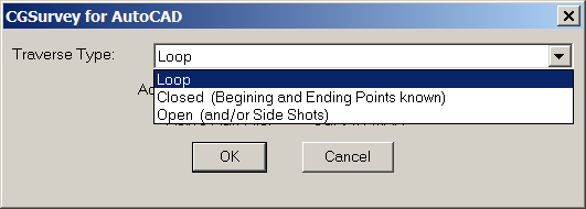 The following figures show examples of the
three traverse types. The H.I. and rod height entries are optional
(if Elevations are on). These are examples of a single
distance/angle entry. Each type traverse may be placed in a
separate raw data file and reduced into a single coordinate file.
However, with the use of special codes you can combine traverses in
a single raw data file (See the
CGEditor chapter).
The following figures show examples of the
three traverse types. The H.I. and rod height entries are optional
(if Elevations are on). These are examples of a single
distance/angle entry. Each type traverse may be placed in a
separate raw data file and reduced into a single coordinate file.
However, with the use of special codes you can combine traverses in
a single raw data file (See the
CGEditor chapter).
Traverse Reduction Types:
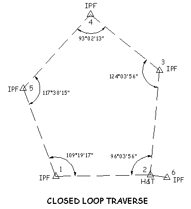
Closed Loop Traverse
Closed Loop Traverse Beginning
and Ending at Ending at Known points
Shows above is closed traverse beginning on two known points
(1 and 2) and ending on two known points (4 and 5). With this
type of traverse, both a linear and angular closure can be
calculated. 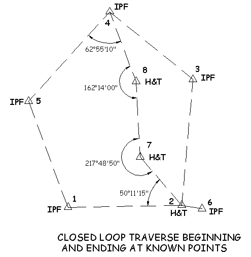
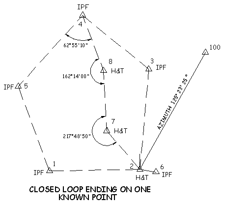
Closed Loop Ending on One Know
Point
Shown above is a traverse that begins on two known points, or a
single known point and a back sight azimuth, and ends on one known
point.
This situation sometimes occurs when you begin on two known points
(or a single known point and a back sight azimuth) and end on one
known point. In this case only a linear closure is
possible.
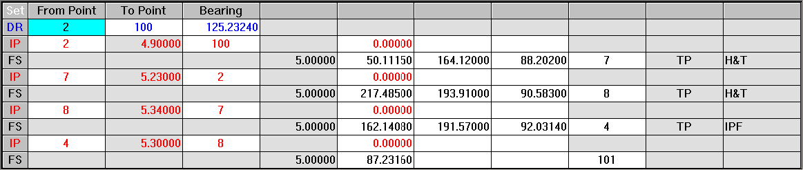
In order to reduce this type of traverse you must use the CGEditor
to enter data not gathered in the field.
Points 2 and 4 are the known beginning and ending points.
Points 100 and 101 do not exist.
We have entered a back sight reference bearing (N 25° 23’ 25” E)
from 2 to 100.
Line 8 is a dummy setup (we never setup on point 4 and back sighted
point 8.
Line 9 shows a dummy angle to the dummy point 101.
Reduce the traverse as a closed Traverse Beginning and Ending on
Known Points.
When the traverse is reduced you will have to enter one of the
following:
The coordinates of point 101
The bearing from point 4 to 101.Or press <esc> for no angular
closure.
If you choose no angular closure, the traverse will be reduced but
will report only a linear closure. The adjustment will be
made assuming no angular error.
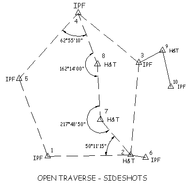
Open Traverse
An Open Traverse is either an open ended traverse which ties into
no known points or a file containing only side shots. In both cases
no adjustment is possible.
Note: The data shown in the CGEditor views accompanying the four
illustrations include instrument height (HI) and rod height
entries. However, if you have elevations turned off,
these entries are optional. Also, the examples use
single distance and angle entries but multiple measurements are
allowed.
In these figures each traverse has been placed in a separate raw
data file. However, with the use of special codes you
can combine multiple traverses in a single raw data file.
Notes on Traverse Types and
Reduction
Closed and Azimuth Traverses: If you are running azimuth traverses,
the angle to the side shot is calculated and stored instead of the
azimuth. After the traverse has been reduced and adjusted, the
angles are used to calculate the side shot coordinates. Thus the
side shots are always relative to the instrument point and
backsight point used in their location. The first azimuth in
the raw data file will be considered a reference azimuth and will
be held.
Reducing Loop
Traverses:
If there is at least one reference bearing in the raw data file
being reduced you will not be asked for a starting bearing. If the
instrument point coordinates at the first reference bearing exists,
you will not be asked to enter the starting coordinates or
elevation. The traverse reduction will begin from the first
reference bearing in the raw data file, not necessarily the first
instrument point.
If you have more than one reference bearing in the raw data file,
the angular closure and adjustments will be from one reference
bearing to the next. In other words, all reference bearings will be
held as correct, and any angle adjustment will be done from one to
the next. This feature was designed for those surveyors who perform
Solar or Polaris observations at intermediate traverse stations,
and wish to hold the observed bearing at those stations (the
bearings will of course change when the coordinates are adjusted,
unless you use Crandall’s Rule which does not change
bearings)..
Reducing Open Traverse:
Any Reference Bearings found in the raw data file for an Open
traverse will be ignored (except the starting reference
bearing/azimuth to the back sight point).
Traverse Reduction: Closed
Loop
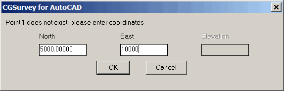
If the first instrument point in the raw data file does not exist,
you will be asked to enter the coordinates for that
point.
 If the first back sight point
in the raw data file does not exist and you do not have a reference
bearing/ azimuth to the back sight point in the raw data file, you
will be given the choice of entering one of the following:
If the first back sight point
in the raw data file does not exist and you do not have a reference
bearing/ azimuth to the back sight point in the raw data file, you
will be given the choice of entering one of the following:
Back sight point
coordinates
Bearing from the first instrument
point to the first back sight point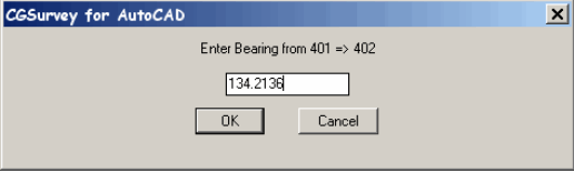 If you are processing a Closed Traverse
that Begins and Ends on known points, and the last (tie) instrument
point in the raw data file does not exist, you will be asked to
enter the coordinates for that point. If the last foresight point
in the raw data file does not exist and you do not have a reference
bearing/azimuth to the foresight point in the raw data file, you
will be given the choice of entering one of the following:
If you are processing a Closed Traverse
that Begins and Ends on known points, and the last (tie) instrument
point in the raw data file does not exist, you will be asked to
enter the coordinates for that point. If the last foresight point
in the raw data file does not exist and you do not have a reference
bearing/azimuth to the foresight point in the raw data file, you
will be given the choice of entering one of the following:
Foresight point
coordinates
Bearing from the last instrument point to the last foresight point
(the last instrument and foresight point are the tie points
necessary for linear and angular closure calculations).
Note: The bearing from the
first instrument point to the first back sight point, and the
bearing from the last (or tie) instrument point to the last (or
tie) foresight point will be treated as reference bearings (held
fixed). These four points will not be adjusted. If there are any
reference bearings in the raw data file, the angular closure and
adjustments will be from one reference bearing to the next, just as
in Loop Traverses.
Since you may have many foresights from the instrument tie point
(side shots), you will be asked to enter which foresight point you
will be tying into (unless there are no side shots at the last
instrument point).
The traverse will begin by the coordinates found in the coordinate
file for the first instrument point and backsight point (coordinate
values can be placed directly into the raw data file). The traverse
will then be calculated. When the traverse is finished, the
coordinates for the last instrument point and foresight point in
the raw data file will be read from the coordinate file (or raw
data file) in order to calculate the angular, vertical and
horizontal closure.
If Elevations are ON you will be shown the elevation control found
in the Raw Data and Coordinate files that pertains to your
traverse. If no elevation control is found none will be shown and
you will have to ADD control. Your elevation control can be
anywhere in the traverse. It does not have to be on the first
point.
You will have the following option
at the command line:
Point
Elevation
1 500.00
[Add/Change/Delete/Go/aBort]: <G>g
Select Add to add points to
elevation control: A
Select Change to change the
elevation assigned to a point in the elevation control:
C
Select Delete to remove a point
from the elevation control: D
Select Go to calculate elevations:
G
Select aBort to quit without
calculating elevations B
Select the appropriate option and
the elevations will be calculated based upon the supplied
information.
At this point you will get two closure reports:
The first report is before angle
adjustment:
********** Closure Report **********
Total angular error: -0°00'06"
Angular error per point: -0°00'01"
Correct Ending Coordinates, North: 5000.00000 East: 5000.00000
Ending Coordinates, North: 5000.04008 East: 5000.00421
Error, N: 0.04 E: 0.00 Total: 0.04 Brg: S 05°59'43"W
Distance Traversed: 2470.51 Closure: 61308
The Second Report is after angle
adjustment:
********** Closure Report **********
Total angular error: 0°00'00"
Angular error per point: 0°00'00"
Correct Ending Coordinates, North: 5000.00000 East: 5000.00000
Ending Coordinates, North: 5000.04314 East: 5000.01593
Error, N: 0.04 E: 0.02 Total: 0.05 Brg: S 20°16'08"W
Distance Traversed: 2470.51 Closure: 53721
Following the angular adjustment
the reduced traverse will be displayed:
Adjusted by Least Squares
Bearing
Distance
Northing
Easting
Elevation Pt
ID Code Description
5000.00000
5000.00000
500.00
1 1
TP1 2
N 00°00'00"E 242.12
5242.12397
5000.00000
496.39
2 1
tpns
N 74°41'24"E 199.78
5294.87495
5192.69243 467.97
3 1
tpns
N 00°22'42"W 148.48
5443.34679
5191.71202
460.90
4
1
tpns
N 04°35'35"W 310.32
5752.67444 5166.86125
458.07
5
1 tpns
S 83°11'32"W 300.98
5716.99780
4868.00744
473.72
6
1
tpns
S 84°09'21"W 290.03
5687.46658
4579.48877
472.10
7
1
tp hole
S 13°25'02"E 137.70
5553.52582
4611.44085
484.33
8
1
tpns
S 05°29'41"E
234.70 5319.90709
4633.91387
501.54
9
1
tpns
S 12°52'27"E 308.42
5019.23837
4702.63376
517.34
10 1
tpns
S 86°17'54"E 297.99
5000.00000
5000.00000
500.00
1
1
TP1 NAIL
Sq. Feet: 341547 Acres: 7.8
Once the traverse is reduced the
side shots will be computed and displayed:
Side Shots
Angle
Distance
Northing
Easting
Elevation
Pt ID Code
Description
Inst.Pt.: 1 Bs.Pt.: 10
148°15'53" 123.43
5058.01266
5108.95161
489.96 47
3 ipf1otp
97°53'24"
46.81
5045.85154
5009.40500
499.25 48
2 ip4rb
17°33'40"
96.60 5035.03240
4909.97367
506.27
49 2
ipf4rb
Inst.Pt.: 2 Bs.Pt.: 1
255°33'17" 93.22
5265.37939
5090.27763
480.73
25 4
ipf1\2" ctp
146°29'54" 17.38
5256.61928
4990.40516
500.49 26
4 ipf1\2" ctp
Inst.Pt.: 3 Bs.Pt.: 2
297°01'47" 18.33
5276.92239
5188.96820
468.73
27
4 ipf1#ctp
Inst.Pt.: 4 Bs.Pt.: 3
10°21'19"
65.64 5378.69600
5180.33917
466.55
28 4
ipf1ctp
159°23'20"
63.27 5502.41856
5169.04898
461.70
29
3 ipf1otp
113°52'33" 138.30
5498.48975
5064.87673
483.03 30
4 ipf1\2" ctp
113°47'52" 186.84
5517.60975
5020.26008
489.30 31
9 fly
291°56'23" 100.21
5406.52118
5284.90634
455.81 32
9 fly
299°04'02" 111.18
5389.97593
5289.24079
455.88 33
4 ipf1ctp
Inst.Pt.: 5 Bs.Pt.: 4
39°33'59" 47.28
5713.93615
5139.76338
458.30
34 4
ipf1ctp
260°33'36" 119.08
5781.54910
5282.38627
464.12 35
2 ipf4rb
72°51'12" 136.19
5702.23225
5040.36168
469.98
36 4
ipf1\2ctp
Inst.Pt.: 8 Bs.Pt.: 7
32°47'04" 103.73
5651.38227
4645.83837
475.70 37
9 nf
150°46'50" 209.58
5399.34540
4753.39990
512.22 38
9 fly
104°48'11" 144.87
5550.02257
4756.26507
497.59 39
9 fly
Inst.Pt.: 10 Bs.Pt.: 9
156°21'56" 66.78
4965.56171
4742.36495
517.21 46
9 stk
********** Elevation Calculations - Elevations Adjusted
**********
Elevations from Points: 1 -> 1
Vertical Err: -0.01, Distance Traversed: 2470.51
The calculate points will be stored in the coordinate file. There
is an overwrite protection built into the software. If a point
already exists in the coordinate file you will have the following
options: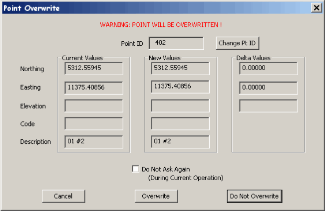 CANCEL: will terminate the process of
storing coordinates.
CANCEL: will terminate the process of
storing coordinates.
OVERWRITE : will overwrite
the existing point.
DO NO OVERWRITE: skip to the next point. If you have the
“Do Not Ask
Again” box checked, OVERWRTE will overwrite all points
without asking,
DO NOT OVERWRITE: will only
write NEW points to the coordinate file.
Traverse Reduction: Open Traverse/Side Shots
When reducing these types of traverses, no adjustments are
possible. The coordinates for instrument points and back sight
points will be pulled from the coordinate file (or raw data file)
and used to calculate and store the foresights. This option allows
you to occupy newly created points.
Coordinates of back sight points will be calculated only if a
distance has been entered to the back sight point and the back
sight point does not exist in the coordinate file.
If you are back sighting a point that does not exist in the
coordinate file and the raw data file does not contain a reference
bearing or azimuth to the back sight point, you will be given
the choice of entering one of the following:
Coordinates of the back sight
point
Bearing from the instrument point
to the back sight point
If you choose to enter the bearing and there is no
distance to the back sight point in the raw data file (thus making
it impossible to calculate its coordinates), and you later occupy
that point, you will be asked to enter the real coordinates of the
point.
If you are backsighting a point that does exist, and you have a
distance measurement to the backsight point in the raw data file,
we will show a warning if the inversed distance from the coordinate
file does not match the measured distance within the tolerances set
in the CGTools->Global Options->Traverse Options dialog.
A table will be printed containing
the following:
Side Shots
Angle
Distance
Northing
Easting
Elevation Pt ID
Code Description
Inst.Pt.: 1 Bs.Pt.: 10
148°15'53" 123.43 5058.01266
5108.95161
489.96 47
3
ipf1otp
97°53'24" 46.81
5045.85154
5009.40500
499.25 48
2 ip4rb
17°33'40" 96.60
5035.03240
4909.97367
506.27 49
2 ipf4rb
Angle Adjustments
If you have set Adjust Angles in the Traverse Options dialog box,
all angles will receive equal adjustment. If there is more than one
reference bearing, the angles will be adjusted equally between
reference bearings. You will be shown the closures before and after
the angle adjustment.
NOTE: If you are going to
use the Least Squares Adjustment, you should not adjust the angles.
Angular adjustment is part of the Least Squares Adjustment
process.
Elevation Adjustment
If you have set Adjust Elevations in the Traverse Options dialog
box, the elevations will be adjusted in proportion to the lengths
of the lines (the longer the line, the more the adjustment).
Least Squares, Crandall’s and
Compass Rule
If you select any of these adjustment options the coordinates will
be adjusted with the appropriate method.
Find Bad Angle
If you have a bad angular closure, select Find Bad Angle in the
Traverse Options dialog box instead of an adjustment type. This
function will not create or store any coordinate points.
NOTE: This option cannot be
used with Azimuth Traverses.
You will see the following
report:
Total angular error: 0ø00'07"
Angular error per point: 0ø00'01"
Correct Ending Coordinates, North: 10000.00000 East:
10000.00000
Ending Coordinates, North: 10000.05876 East: 9999.95840
Error, N: 0.05876 E: -0.04160 Total: 0.07200 Brg: S 35°17'49"E
Distance Traversed: 1492.10800 Closure: 20725
Instrument point: 1, Error: 0.07200, Closure: 20725
Instrument point: 2, Error: 0.08249, Closure: 18089
Instrument point: 3, Error: 0.08284, Closure: 18013
Instrument point: 4, Error: 0.07542, Closure: 19785
Instrument point: 5, Error: 0.06751, Closure: 22103
Worst Closure: 18013
Average Closure: 19620
Possible bad angle at instrument point: 5, Closure: 22103
In the above example, there were 5 traverse points. The traverse is
reduced five times, beginning at each traverse point. The starting
instrument point that produces the best closure is shown as having
the bad angle. All closures are shown.
OTHER METHODS OF TRAVERSING
Every surveyor has his own unique methods when it comes to
traversing. This section describes and shows examples of four
additional entry methods.
Notice in the sample traverses there is a distance and vertical
angle recorded for each foresight and back sight. This is optional,
but you need at least one distance to each foresight.
Where both foresight and back sight distances are recorded,
distances will be averaged when reduced
Side shots may be entered along with traverse information. You may
turn more than one angle to side shots if you wish.
A description and/or code only needs to be entered once for a given
foresight point.
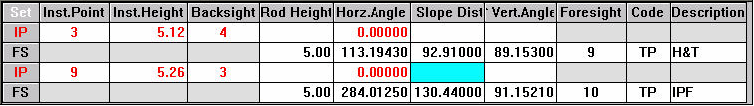
Single Position with Direct and Reverse Angles
Perform this method as follows:
Shoot the back sight.
Turn to a foresight.
Record the angle and distance.
Plunge the instrument.
Take another reading (reversed) to the foresight. You may do this
to traverse points and side shots.
Turn back to the back sight with the instrument reversed.
Record another angle to the back sight.
The final angle in each set for each instrument point must be a
reverse reading to the back sight.
The angle in the instrument for the first back sight will be
subtracted from the first angle to each foresight. The final
(reverse) angle to the back sight will be subtracted from the
second angle to each foresight. The two resulting angles will then
be averaged to give you an angle to the foresight. All distances
recorded will be averaged.
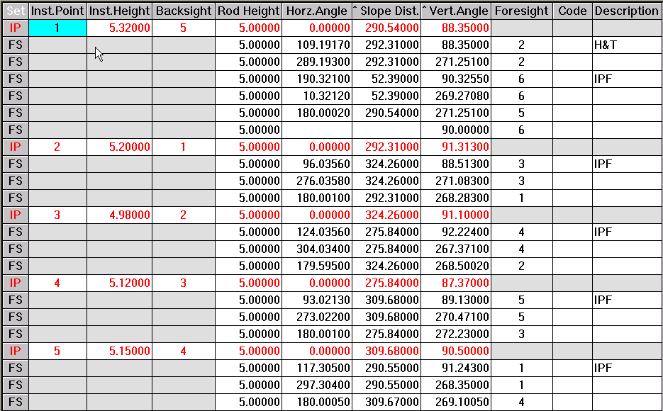
Single Positions with Multiple Direct and Reverse Angles
Entering multiple sets of direct and reverse angles is very much
like the preceding example where 1 direct and reverse set was
entered. The only thing to remember is that each direct and reverse
pair is a set. When another set is entered, it begins with a back
sight direct angle (recorded like a foresight), has direct angles
and reverse angles to the foresights, and ends with a reverse angle
to the back sight. Do not begin a new instrument point for the
second set, merely record a new back sight angle and continue with
the procedure through each foresight, and end with another reverse
angle to your back sight.
Azimuth Traverses
Azimuths are entered into a file with the azimuth to each foresight
entered in the Foresight data entry line at the azimuth column.
NOTE: If you are running a
Closed Loop Traverse, a reference azimuth must be placed at the
last instrument point if you wish to adjust the angular error.
The reference azimuth is the correct azimuth from the last
instrument point in the raw data file to the first instrument point
(or last foresight).
Traverse with Doubled Angles
 Each new instrument setup requires a 0 to the back
sight. The first angle to the foresight is the single angle. This
angle is locked into the gun and the back sight is retaken. The
second angle to the foresight is the doubled angle. You can double
angles to side shots.
Each new instrument setup requires a 0 to the back
sight. The first angle to the foresight is the single angle. This
angle is locked into the gun and the back sight is retaken. The
second angle to the foresight is the doubled angle. You can double
angles to side shots.
Loop Traverse Beginning and Ending on External Reference
Azimuths
This type of traverse occurs frequently. The example below shows a
Loop Traverse that begins on an external reference azimuth and ends
on an external reference azimuth. Even though this traverse closes
on itself, it must be reduced as a Closed Traverse Beginning and
Ending at Known Points.
Point 100 is a dummy point on the azimuth line. Line 3 shows a
reference bearing from point 1 to 100 (negative means from ip to
bs) of S00-00-00E.
Line 16 shows the same reference bearing.
Point number 100 need not exist in the coordinate file and will not
be calculated, but a dummy backsight and foresight point number
must be entered into the raw data file.
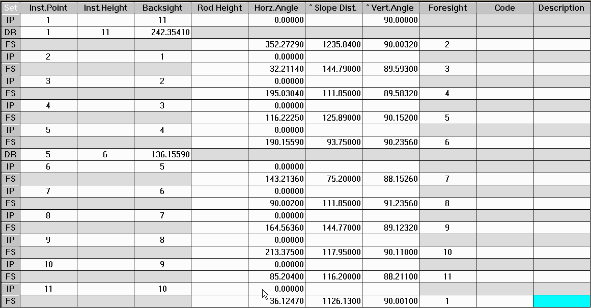
Use Of Reference Bearings and Azimuths
Reference Bearings and Azimuths are entered by Adding or Inserting
a Reference Bearing data entry line. For example:
DR 1-2 123.4523
The direction from point 1 to point 2 is N23-45-23E.
Reference bearings and azimuths are optional (except for Closed
Loop Azimuth Traverses). If a reference bearing is used, that
direction will be held during the reduction process. More than one
reference bearing may be used. The data below shows a raw data file
using multiple reference bearings:
The previous data represents a loop traverse. If you choose to
adjust angles, all angles will be adjusted from one reference
bearing to the next (angles 1-5, 6-1). Angular closure information
will also be shown from one reference bearing to the next. See the
Reduction section of this chapter for more specific information on
the use of reference bearings with different types of
traverses.
Except for an initial reference bearing to the back sight point,
reference bearings will be ignored for Open Traverses (no
adjustments are available).
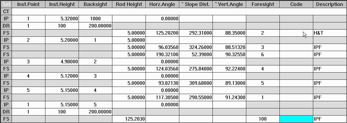
Multiple Traverse Codes in a Single File
This sample is of a raw data file that contains multiple traverse
codes in a single file: ET end main loop traverse
Scale factors are placed after Instrument Point data entry lines.
Any text following a LT, CT, OT or ET marker is used for comments.
Notice that the codes MUST precede the first instrument setup that
begins the traverse.
The Foresight Tie Point in the previous example is necessary
because there is a side shot (point #25) at the end of the Closed
Traverse. The reduction routine does not know whether you are tying
into point 25 or point 2 Pull Down Menu Location:CGTrav\ Reduce
Traverse
Pull Down Menu Location:CGTrav\ Reduce
Traverse
KeyBoard Command:RT,
CG_REDUCE_RAW
Prerequisite:Open Raw file
*.CGR