Draw
This feature automates the production of a drawing that can contain
specific points, lines, arcs and curve fit lines. The draw option
also acts as a Cogo function in that it will calculate the PC, PT
and radius points of curves and has the ability to calculate points
by traversing and intersection.
Prompts
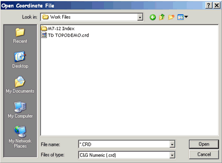
After choosing the Draw command, if a coordinate file is not open,
you will be asked to open one.
After opening the coordinate file,
you will be asked to select the points you want to map:
Choose initial points for base
selection set from coord. file: (Enter when done)
[All/Block/Code/Desc/Elev/Pt-group/Limits/Radius/Select]:
Next, you will be asked whether
you want to store elevations at calculated PC, PT, and radius
points: When locating items like back of curb you may
need to note the beginning and ending of curves. The points
located are never exact as far as the beginning and ending of the
curve, but when noted in the mapping routine the application will
compute a PC, PT and Radius using the best fit routine and you can
choose to store theses points or not.
Note: If Auto Point Plot is
ON as specified in the Graphic Options tab of the C&G Options
dialog, points will be plotted and lines, arcs and/or curve fit
lines are drawn when indicated by Mapping Codes found in the point
descriptions.
Mapping Codes Used by the Draw feature
The map codes used by the Draw feature must be placed in the
description field for each point in the coordinate file that is to
be “Mapped”.
Below is the list of map codes:
BL - Begin Line
EL - End Line (optional)
CL - Close Figure
PC - Begin Curve (tangent to previous line)
OC - Point on Curve (begin/end non-tangent curve)
PT - End Curve (tangent to next line)
RP - Radius Point
CF - Curve Fit (spline fit to irregular curves)
CC - Compound Curve
RC - Reverse Curve
Mapping Codes can be upper or lower case. The map code MUST
be followed by an asterisk and a line description for the line that
is being drawn. For example: BL*CURB1, where CURB1 is the
line description for the line you are beginning. It is OK to have
spaces between the code, asterisk and line description, but it is
not necessary.
For example:
Point ID
Description
5
BL*
CURB1 BL*SW1 WV
6
CURB1
7
SW1 PP
8
PC*
CURB1
9
FH
10
PT* CURB1
11
CURB1 SW1
12
OC* SW1
13
SW1
14
SW1
15
SW1
16
OC* SW1
17
CL* SW1
18
BL* CURB1
Important Note: Mapped
lines are connected in ascending order by point ID. The point ID’s
are always saved in the coordinate file in increasing order. Since
the coordinate file is used to perform the Map Drawing and the
point ID sequence is produced when the raw data is reduced, it
follows that the order of field location of the points will
determine point ID sequence order when the lines are mapped.
In the sample sequence above:
Point 5 begins two lines, Curb1 and SW1. Curb1 and SW1 are line
descriptions. A line description must be a whole word (no spaces).
WV (water valve) is not the
beginning of a line because an asterisk does not precede it.
For example:
5
BL*CURB1 BL*SW1 WV
The Curb1 line will be drawn from point 5 to point 6 to point
8. This begins a curve tangent to the line from 6 to 8
continuing to point 10. The curve is tangent to the line from
10 to 11. Since point 18 begins a new Curb1, point 11 is the end of
the first Curb1 line (the EL code is not required in order to end a
line).
A second line (SW1) will be drawn from 6 to 7 to 11 to 12. At point
12 a non-tangent circular curve begins and continues through points
on the curve at 13, 14, and 15. The non-tangent curve ends at point
16 and lines continue from 16 to 17 to 1 (the CL code closes the
figure). In creating the non-tangent curve from point 12 through
point 16, points 13-15 are used by the Map Draw feature in the
calculation of the best fit circular curve.
In addition to the lines drawn, the symbol specified for the WV
description in the description table (see CGMngmt) will be placed
at point 5 and, at point 7, the symbol specified in the description
table for the description PP will be drawn.
As demonstrated in the above example, you may combine multiple
codes and line descriptions within a single point description.
For example:
Point
ID
Description
20
BL*SW1 BL*CURB1 CURB2 EL*CURB3
CL*CURB4
In this example point 20 begins the SW1 line and the CURB1 line. It continues the
CURB2 line. It ends
the CURB3 line and it
closes the CURB4 line.
The Begin Line Code:
All lines must start with a BL code. No lines will be connected to
a point unless a word in the point description matches a BL* line
name.
The Close Line Code: The close line code (CL) causes the Draw Map
feature to connect the CL point to the BL point. You can also use
the CL command to traverse. Thus you may place dimensions after a
CL command.
For example:
Point ID
Description
20
*BL*BLD1
21
CL*BLD1+10.1+10.2-20.3+50.6 EL*SW1
Note: The FC-48 data
collector does not allow ‘+’ characters in description field.
Because of this, the ‘/’ character can be used instead of the ‘+’
character in all the CL examples.
In the above example a line will be drawn from point 20 to point
21. The following points will then be calculated through a traverse
sequence (assume the next point available is 100):
Occupied
Pt BS
Pt Angle
Distance New Point
21
20
90
10.1
100
100
21
90
10.2
101
101
100
270
20.3
102
102
101
90
50.6
103
Point 103 will then be connected to point 20 to close the BLD1
line. Please note that point 21 is also the end of the SW1
line.
In a CL mapping code sequence, a negative dimension turns -90
degrees from the back azimuth and a positive dimension turns +90
degrees from the back azimuth. Both the ‘+’ and ‘-’ symbols are
required but, as noted above, the ‘/’ symbol can be substituted for
the ‘+’ where necessary.
This same figure could also be drawn using the following
sequence:
Point ID
Description
20
BL*BLD1
21
CL*BLD1+10.1+10.2-20.3+
Note that the closing
distance was not included in the description sequence. See the
following examples.
If you have located two corners of a rectangle, you may use the
following short cut:
Point ID
Description
20
BL*BLD1
21
CL*BLD1+50.6+
In the above example a line will be drawn from point 20
to point 21. The following points will then be calculated through a
traverse sequence (assume the next point available is 100):
Occupied Pt BS
Pt Angle
Distance New Point
21
20
90 50.6
100
Point 101 will be calculated by a bearing-bearing intersection.
Then point 101 will be connected to point 20. The first ‘+’ sign
determines the direction used to calculate point 100. The
description ending in a ‘+’ sign has the same effect as ending in a
‘-’ sign: if there is no dimension after the last ‘+’ or ‘-’ sign,
the last point will be calculated by a bearing-bearing
intersect.
If you have located three corners of a rectangle, you may use the
following short cut to define the lines to be drawn:
Point ID
Description
20
BL*BLD1
21
BLD1
22
CL*BLD1+
In the above example lines will be drawn from point 20 to 21 to 22.
The missing corner will be calculated using a bearing-bearing
intersect and stored. As noted earlier, ending in a ‘-’ sign
instead of a ‘+’ sign has the same end result.
Curve Codes
Anytime a circular curve is encountered, 3 new points may be
calculated and stored in the coordinate file. These points are the
PC, PT and radius point of the curve. It is necessary to calculate
these points during automated mapping since the field points are
only approximations of a perfect curve. They will automatically be
assigned point numbers (regardless of the Auto Point Numbering
setting). The points calculated during automated mapping of curves
will begin with the coordinate files current high point number plus
1.
If the beginning of a line is also the beginning of a curve, one of
the following formats must be used:
Point ID
Description
10
BL*SW1 CF*SW1 (begin a curve-fit line)
or 10
BL*SW1 OC*SW1 (begin a non-tangent circular
curve)
or
10
BL*SW1
PC*SW1 (begin a tangent circular curve)
Once a curve has begun, all matching line descriptions will be
considered points on the curve until the curve is ended. A
curve is ended with either a PT*, OC*, or CF* code.
For Example:
Point
ID Correct Sequence
Incorrect Sequence
10
OC*SW1
(Begin
SW1)
11
SW1
OC*SW1 (will end SW1)
12
SW1
OC*SW1 (will end SW1)
13
SW1
OC*SW1 (will end SW1)
14 OC*SW1
(End SW1)
The first OC begins the curve. The next OC ends the curve. All the
points between them are on the curve. The same is true for curve
fit (CF*).
If a curve is either tangent (in), tangent (out) or tangent (in)
& tangent (out), you only need two points to define the
curve:
Point ID
Sample 1 Sample
2 Sample 3
10
PC*CURB1 PC*CURB1
OC*CURB1
11
PT*CURB1 OC*CURB1
PT*CURB1
Otherwise you will need at least three points on a curve:
Point
ID
Description
12
CF*CURB1
13
CURB1
14
CF*CURB1
The RP Mapping Code
If you use the RP code (radius point), it will be used regardless
of the number of points on the curve. The radius will be calculated
by averaging all the distances from the radius point to the points
on the curve.
Best Fit Circular Curve Calculations
If you have three or more points on a non-tangent curve, the
best-fit curve solution is used to find the radius point.
If you have three or more points on a tangent curve (either tangent
in, tangent out, or tangent in and out), the best-fit curve
solution is used to determine an approximate radius and radius
point. A dummy point is then calculated on the curve and a curve is
drawn that goes through the dummy point and meets the tangent
criteria (the PC and PT points are shifted up/down the tangent
lines as necessary). If only three points are located, PC, POC and
PT, the curve will always go through the POC point.
If you have only two points (PC and PT) on a tangent curve, the
tangent lines from the PC and PT will be intersected to find the PI
of the curve. The distance from the PI to the PC and the distance
from the PI to the PT will be averaged to obtain a tangent
distance. A new PC and PT point will be calculated on the tangent
line and the radius point will be calculated based on the tangent
and central angle.
Non-Circular Curves
You may use the CF* code for a non-circular curve fit (splines).
The CF code will start a curve fit line. The curve will continue
until a second CF* code is encountered, example:
Point ID
Description
11
CF*SW1
12
SW1
13
SW1
14
CF*SW1
Only use CF to start or end a curve. Notice points 12 and 13 do not
have automated mapping codes.
A smooth curve will be drawn through points 11, 12, 13 and 14. No
new coordinate points are generated with the CF code.
Layers and linetypes for mapped lines and curves
The description table determines the layer in which a mapped line
will be drawn. For mapped lines and curves, only the description
and layer fields in the description table are used.
However, if the default layer is not set, no description table
lookup is performed and the line is drawn on the current
layer.
For example, assume that the default layer has been set and that
the description table contains the following entry:
Desc. No.
Description Layer
Name
5
CURB
Road
Since layer “Road” is specified for description “Curb”, all lines
with descriptions “Curb” will be placed in layer “Road”. Numbers
are not used in the comparisons: Curb1, Curb2, Curb10, etc. are
considered a match for the description “Curb” and will therefore be
placed in layer “Road”.
If a matching description is not found in the description table,
the line is drawn on the default layer (as set in the Graphic
Options tab of the C&G Options dialog box).
Calculated Points
All coordinate points that are automatically calculated and stored
during automated mapping are given a MP point code.
Note: Even though the point
description field can contain Mapping Codes, the point code found
in C&G coordinate files is separate and distinct from the point
description field. All points already having an MP Code are ignored
by automated mapping. This avoids re-mapping points that were
generated during automated mapping and thus were not points
actually located in the field.
Important Note: Consider
the MP point code as a reserved code and do not
use it for field data collection.
The description (e.g., CURB) used for calculated points is the same
as the line description of the points the calculated point is
associated with and reflects the type of calculated point that it
is.
For Example:
Assuming the line description for the following points is “CURB1”
and the points are the PC, PT and radius point of a curve, then the
line descriptions will be:
New Point ID
Point
Code
Description
100
MP
PC CURB1
101
MP
RAD.PT CURB1
102
MP
PT CURB1
Plotting of Points
If Auto Plot Points is “On”, all the selected points in the
coordinate file will be plotted on the screen during the mapping
process. If a default layer is set, Each point will be drawn
on the layer specified in the description table. The points
labels will be configured as specified in the description table.
Any point that does not have a description match in the description
table will either be drawn on the default layer.
Pulldown Menu Location:
CG-Survey >Auto Map>Draw
Keyboard Command: MAP,
CG_MAP_DRAW
Prerequiste:
Coordinate file