This command is for simultaneously creating a .pro file and drawing the road profile. It is typically used when designing a road profile on top of a plotted existing grade profile, where the goal is to minimize cut and fill and keep to a minimum the number for vertical curves and avoid excessively steep grades. It is often necessary to match the starting and ending elevations of existing roads or features. For example, a side road will contact the main road at a fixed, given elevation. One concept to remember is that it may be best to favor a little more fill than cut in the design profile, because if your design template for the road involves ditches, a little bit of cut can lead to significant extra cut volumes due to the ditch placements. The Design Road Profile command works fine when overlaying on profile plots with either matching horizontal and vertical scales or exaggerated vertical scales (e.g. 50 H and 5 V). Just be sure to specify the correct scale settings in the Profile Settings dialog. The procedure is to first specify the on-screen grid and then enter or pick the stations and elevations.
Once two segments have been entered, you will be prompted for the vertical curve length. The vertical curve is a parabola, the typical form used in the United States. If you don't want a vertical curve, enter 0. Otherwise you can directly enter the vertical curve, or enter the sight distance or the K-value from which the vertical curve is calculated. The vertical curve can also be specified to pass through a point or do a best fit through multiple points. This through point option would be useful for hitting an existing feature such as a driveway on the vertical curve. Unequal vertical curves is another option where the vertical curve length going into the PVI differs from the length leaving the PVI. Before using your entry, the vertical curve, sight distance, and K-value are displayed. Object height and eye height are two variables that effect the vertical curve. Their values can be set using the command Profile Defaults.
Notice that the station, elevation and slope at the current position of your cursor crosshairs are displayed in real-time in a small dialog.
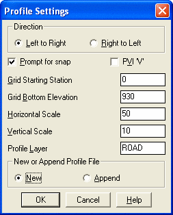
Profile Settings dialog
Profile to Write Dialog Note that you can choose to
append
to an existing road profile, which allows you to continue design work
in
different work sessions. If Append is selected, the cursor will
default
to the end point of the selected profile, which will be treated as a
'PVI'
point, so that you will be prompted for a vertical curve length after
your
very next picked point.
Pick Lower Left Grid Corner <5000.08,3211.24>[endp on]: Pick
a lower left corner for the plotted grid on the screen.
If you have just finished plotting the existing profile, the
program will remember your lower left coordinates, and you just hit
Enter to accept the default values.
Enter station or pick a point (Enter to End): 0
Elevation of PVI: 932.5
Station of second PVI or pick a point (U,E,D,Help): 175
Percent grade entry/Ratio/<Elevation of PVI>: 942
Station of next PVI or pick a point ('U' to Undo, Enter to End):
pick a point
Snap PVI dialog
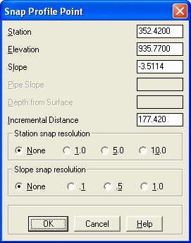
The Snap PVI dialog box appears when you pick a point (if the Prompt for Snap option in the Profile Settings dialog is selected). The station and slope may be changed to the nearest snap value. The elevation is the free variable and it will change to compensate for any snap. To change the elevation, select the elevation edit box and enter the new value. In this example, you might choose a slope snap of 0.1 and if the station was flexible (not fixed, such as the end of the road), you could choose a station snap of 10.
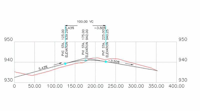
View Table/Unequal/Through pt/Sight Distance/K-value/<Length
of Vertical Curve>: 100
For Crest with
Sight Distance>VC and Vertical Curve => 100.00
Sight Distance => 124.43, K-value => 11.2
Use these values (<Y>/N)? press Enter
Station of next PVI or pick a point ('U' to Undo, Enter to End):
press Enter
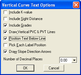
Vertical Curve Text Options dialog box
Pick vertical position for VC text: Pick a position above the
profile grid. The final plot is shown below:
Pulldown Menu Location: Profiles
Keyboard Command: road
Prerequisite: A profile grid
File Names: \lsp\makeprof.lsp, \lsp\vcplot.lsp,
\lsp\profedit.arx, \lsp\profile.dcl