The command uses the X,Y from the selected entities and calculates the Z from a surface model that is stored in a grid (.grd) or triangulation (.flt, .tin) file. For example, this command could be used to generate points representing key locations of design features for stakeout. Choose the lines and arcs of your design with this command to specify the PC's, PT's and endpoints. The results are stored in the current coordinate (.CRD) file and could be transferred to an electronic field book.
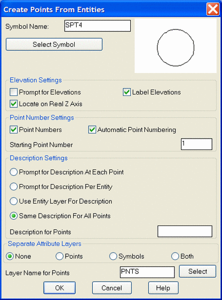
Create Points From Entities Dialog Choose whether to prompt
for descriptions, elevations or point numbers.
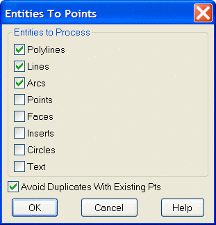
Entities to Process Dialog Choose entities to process.
Source of Surface Model Choose a grid (.GRD) or triangulation
(.FLT, .TIN) file.
Select arcs, faces, line and/or polylines.
Select objects: pick entities
Pulldown Menu Location: 3D Data > 3D Points
Keyboard Command: autoelev
Prerequisite: Create a surface model and entities to convert
File Names: \lsp\autoelev.lsp, \lsp\makegrid.arx