
This command routes runoff through branches, structures and reaches. The dialog first prompts for storm data. Descriptions of these variables are in the TR-20 manual. After the dialog, select the flow lines, structures and reaches that were created by the Draw Flow Polylines, Locate Structure and Locate Reach commands. The program then creates a TR-20 input file called temp.dat in the Carlson exec directory and runs TR-20. The output can be sent to a file, printer or screen from the report viewer. The routine supports the older and newer versions of TR-20 that are more Windows-compatible.
Hydrographs are created at each flow line junction, structure and
reach.
The hydrographs are stored in files with a .h1 extension. These files
are
named automatically and placed in the Carlson data directory.
Hydrographs
entering a structure start with an 'S' and then the structure number.
The
structure number is labeled next to the structure symbol. Hydrographs
entering
a junction start with a 'J' and then the junction number. The junction
number
is also labeled next to the junction.
The next part of the file name is either 'RUN' for runoff, 'OUT' for the hydrograph at the end of the Watershed schematic with two flow lines, one structure and two reaches to be used as input for Hydrograph Development structure, 'REA' for the end of a reach, or 'ADD' for the combination of two hydrographs. A more detailed description of the hydrograph is in the third line of the hydrograph file. The Hydrographs can then be plotted using Draw Hydrograph.
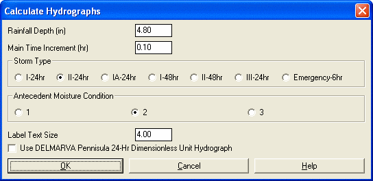
Calculate Hydrographs Dialog
Select flow polylines, structure and reach symbols.
Select objects: pick the objects
Pulldown Menu Location: Watershed
Keyboard Command: runtr20
Prerequisite: A flow polyline. Structures and reaches are
optional.
File Names: \lsp\runtr20.lsp, \lsp\poly3d.arx, \lsp\hydro.dcl,
\exec\tr20.exe