Preferences
Function
This command allows you to customize the Carlson Survey
settings.
Files Tab
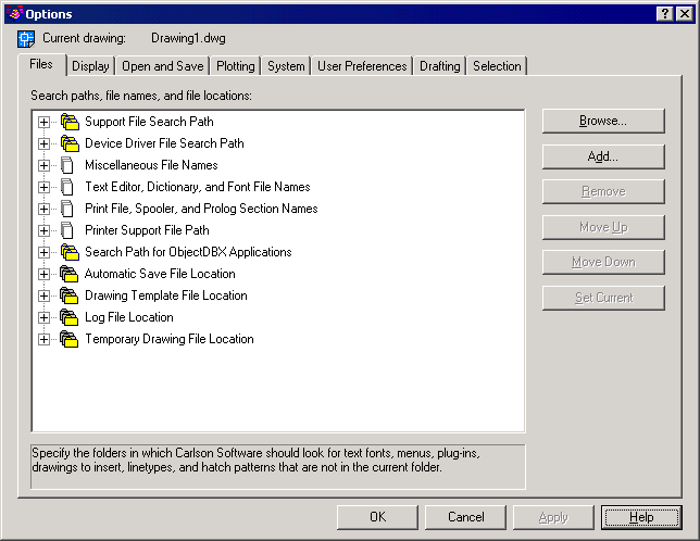
Under the Files Tab, you specify the directories in
which the
program searches for support, driver, menu, and other files. You can
also
specify optional, settings such as which dictionary to use for checking
spelling. Each option under the Files Tab displays a
list of the directories and files used by Carlson
Survey. To specify a location for a directory or file, double-click the
directory or file from the list. Choose Browse and use the Browse for
Folder
dialog box (a standard file selection dialog box) to locate the
directory or
file you want to use.
1 Support
File Search Path: Specifies the directories in which Carlson
Survey searches for support files. In addition to the files required to
run the program, you can include files for fonts, menus, drawings to
insert,
linetypes, and hatch patterns in the support file search path.
2 Device
Driver File Search Path: Specifies where the program looks for device drivers for the video
display, pointing devices, printers, and plotters.
3 Miscellaneous
File Names: Specifies the names and locations of
various types of files.
- Menu File: Specifies the location of the menu file.
- Default Internet Location: Specifies the default
Internet location used
by both the Connect to Internet option on the Help menu, and the Launch
Browser
button on the Standard toolbar.
4 Text Editor, Dictionary, and Font File
Names: Specifies a number of optional settings.
- Text Editor Application: Specifies the text editor
application to use
for editing mtext objects.
- Custom Dictionary File: Specifies a custom
dictionary to use (if you
have one).
- Alternate Font File: Specifies the location of the
font file to
use if Carlson
Survey cannot locate the original font and an alternate font is not
specified in the font mapping file. If you choose Browse, the program
displays
the Alternate Font dialog box, from which you can choose an available
font.
- Font Mapping File: Specifies the location of the
file that
defines how Carlson
Survey should convert fonts it cannot locate.
5 Print File,
Spooler, and Prolog
Section Names: Specifies settings
related to plotting.
- Plot File Name For Legacy Plotting Scripts: Specifies a default name for the temporary
plot files used with plotting scripts created with earlier versions of
Autodesk
products. The default name is the drawing name plus .plt file name. The
default
name used with Carlson
Survey drawings is the drawing name-layout name plus the .plt file name
extension. Some plotting device drivers, however, use a different plot
file
extension name. This option only affects the default plot file name
used for
plotting scripts created with earlier versions of Autodesk products.
- Print Spool Executable: Specifies the application to
use for print
spooling. You can enter the executable file name as well as any command
line
arguments you want to use. For example, you can enter myspool.bat %s to
spool
plot files to myspool.bat and have a unique plot file name
automatically
generated.
6 Printer
Support File Path: Specifies search path settings for printer support files.
- Print Spooler File Location: Specifies the path for
print spool files. Carlson Survey
writes the plot to this location.
- Printer Configuration Search Path: Specifies the
path for printer configuration
files (PC3 files).
- Printer Description File Search Path: Specifies the
path for files with a .pmp
file extension, or printer description files.
- Plot Style Table Search Path: Specifies the path for
files with an .stb or
.ctb extension, or plot style table files (both named plot style tables
and
color-dependent plot style tables).
7 Search
Path for ObjectDBX
Applications: Specifies the path
for ObjectDBX™ application files. You can enter multiple URL addresses
under
this option. (Multiple URLs should be separated by a semi-colon.)
Carlson Survey
searches the specified URLs when an associated ObjectDBX application
cannot be
located. Only URL addresses can be entered in this option.
8 Automatic
Save File Location: Specifies the path for the file created when you select Automatic Save
on the Open and Save tab.
9 Drawing
Template File
Location: Specifies the path for
the template files used by the setup wizards.
10Log File Location: Specifies the path for the log file created
when you select Maintain a Log File on the Open and Save tab.
11Temporary Drawing
File
Location: Specifies the location Carlson Survey
uses to store temporary files. The program creates temporary files on
disk and
then deletes them when you exit the program. If you plan to run the
program
from a write-protected directory (for example, if you are working on a
network
or opening files from a CD), specify an alternate location for your
temporary
files. The directory you specify must not be write-protected.
12Buttons: You use
the
following buttons to manipulate the files and paths.
- Browse: Displays the Browse for Folder or Select a File dialog box, depending
on
what you selected in the List of Folders and Files.
- Add: Adds a search path for the selected directory.
- Remove: Removes the selected search path or file.
- Move Up: Moves the selected search path above the preceding search path.
- Move Down: Moves the selected search path below the
following search path.
- Set Current: Makes the selected project or spelling
dictionary current.
Display Tab
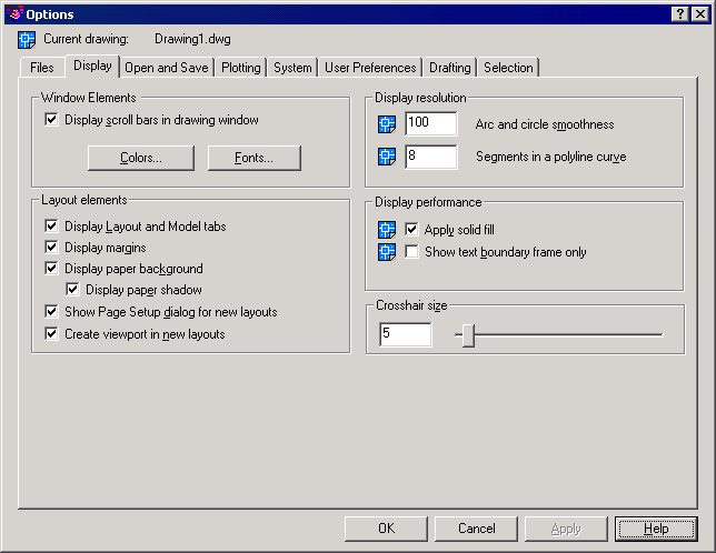
1 Under Window
Elements, you
control display settings specific to the Carlson
Survey drawing environment.
- Display Scroll Bars in Drawing Window: Specifies
whether to display scroll bars at
the bottom and right sides of the drawing area.
- Colors: Displays the Color Options dialog box. Use this dialog box to specify
the colors of elements in the window.
- Fonts: Displays the Command Line Window Font dialog box. Use this dialog box
to
specify the font for the command line text.
2 Under Layout
Elements, you
control options for existing and new layouts. A layout is a paper space
environment in which you can set up drawings for plotting.
- Display Layout and Model Tabs: Specifies whether to
display the layout and
Model tabs at the bottom of the drawing area.
- Display Margins: Specifies whether margins are
displayed in a
layout. Margins appear as dashed lines. Objects drawn outside of the
margins
are clipped or omitted when the drawing is plotted.
- Display Paper Background: Specifies whether a
representation of the
specified paper size is displayed in a layout. The paper size and plot
scale
determine the size of the paper background.
- Display Paper Shadow: Specifies whether a shadow is
displayed
around the paper background in a layout.
- Show Page Setup Dialog for New Layouts: Specifies
whether the Page Setup dialog box
is displayed when you create a new layout. Use this dialog box to set
options
related to paper and plot settings.
- Create Viewport in New Layouts: Specifies whether a
viewport is created when
you create a new layout.
3 Under Display
Resolution, you
control the quality of the display of objects. If you set high values
to
improve display quality, the impact on performance is significant.
- Arc and Circle Smoothness: Controls the smoothness
of circles, arcs,
and ellipses. A higher number produces smoother objects, but requires
more time
to regenerate, pan, and zoom the objects. You can improve performance
by
setting this option to a low value such as 100 for drawing, and
increasing the
value for rendering. The valid range is 1 to 20,000. The default
setting is
100. This setting is saved in the drawing. To change the default for
new
drawings, consider specifying this setting in the template files on
which you
base your new drawings.
- Segments in a Polyline Curve: Sets the number of
line segments to be
generated for each polyline curve. The higher the number, the greater
the
performance impact. Set this option to a low value such as 4 to
optimize
performance for drawing. Values range from -32767 to 32767. The default
setting
is 8. This setting is saved in the drawing.
4 Under Display
Performance, you
control display settings that affect Carlson
Survey performance.
- Apply Solid Fill: Controls whether solid fills in
objects are
displayed. Objects with solid fill include multilines, traces, solids,
all
hatches (including solid-fill), and wide polylines. You must regenerate
the
drawing by using REGEN for this setting to take effect. This setting is
saved
in the drawing. Clear this option to optimize performance.
- Show Text Boundary Frame Only: Displays the frames
for text objects instead
of displaying the text objects. After you select or clear this option,
you must
use REGEN to update the display. This setting is saved in the drawing.
Select
this option to optimize performance.
5 Under
Crosshair Size, you
control the size of the crosshairs. The valid range is from 1 to 100
percent of
the total screen. At 100 percent, the ends of the crosshairs are never
visible.
When the size is decreased to 99 percent or below, the crosshairs have
a finite
size, and the ends of the crosshairs are visible at the edge of the
drawing
area. The default size is 5 percent.
Open and Save Tab
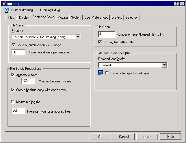
Under the Open and Save Tab, you control options that
relate to
opening and saving files.
1 Under File
Save, you control
settings related to saving a file in Carlson
Survey.
- Save As: Displays the valid file formats used when
saving a file with SAVE
and SAVEAS. The file format selected for this option is the default
format that
all drawings are saved as when you use SAVE or SAVEAS. Saving an
Carlson Survey
file to any DXF format affects performance. Set the Save As option to
Carlson Survey
2000 Drawing to optimize performance while saving.
- Save a Thumbnail Preview Image: Specifies whether an
image of the drawing
should be displayed in the Preview area of the Select File dialog box.
- Incremental Save Percentage: Sets the percentage of
potential wasted
space in a drawing file. When the specified percentage is reached, the
program
performs a full save instead of an incremental save. Full saves
eliminate
wasted space. If you set Incremental Save Percentage to 0, every save
is a full
save. Although incremental saves
increase the size of your drawing, avoid setting a very low value. Low
values
degrade performance because the program performs time-consuming full
saves more
often. For optimum performance, set the value to 50. If hard disk space
is
scarce, set the value to 25. If you set the value to 20 or less,
performance of
the SAVE and SAVEAS commands slows significantly.
2 File Safety
Precautions
settings help you avoid data loss and detect errors.
- Automatic Save: Saves your drawing automatically at
the interval you specify. You
can specify the location of all Autosave files by using the
SAVEFILEPATH system
variable. SAVEFILE (read-only) stores the name of the Autosave file.
- Minutes Between Saves: Specifies how
often the drawing is saved when using Automatic Save. The value is
stored in
SAVETIME.
- Create Backup Copy with Each Save: Specifies whether
a backup copy of a drawing
is created when you save the drawing. The backup copy is created in the
same
location as the drawing. The ISAVEBAK system variable controls whether
a backup
copy of the drawing is created.
- Maintain a Log File: Specifies whether the contents
of the text
window are written to a log file. To specify the location and name of
the log
file, use the Files tab in the Options dialog box.
- File Extension for Temporary Files: Specifies a
unique extension that allows you
to identify your temporary files in a network environment. The default
extension is .ac$.
Retrieving Autosave (backup) Files
If you experience a system crash, it is
possible to retrieve the last
Autosave file and continue working from this last save. Retrieving Autosave files is not a
substitute for regularly saving your work manually!
Autosave files have the extension .sv$. To locate these files,
use the Windows Search routine to locate files with this extension
(e.g. search *.sv$). The most recently modified .sv$ file will
likely have your most recent work.
Once you locate the .sv$ file, navigate to its location using Windows
Explorer. Rename the file extension to .dwg, and open the file
using your Carlson Software. Once the file is opened, confirm
that it is your drawing and then use the SaveAs command (described
above) to save the drawing to the location of your choosing.
3 Under File
Open, you control
settings that relate to recently used files and open files.
- Number of Recently Used Files to List: Controls the number of recently used files that are listed in the
File menu
for quick access. Valid values are 0 to 9.
- Display Full Path In Title: Displays the full path
of the active drawing
in the drawing's title bar, or in the Carlson
Survey title bar if the drawing is maximized.
4 Under
External References
(Xrefs), you control the settings that relate to editing and loading
external
references.
- Demand Load Xrefs: Controls demand loading of xrefs.
Demand
loading improves performance by loading only the parts of the
referenced
drawing needed to regenerate the current drawing. External Reference
File
Demand Load is also controlled by the XLOADCTL system variable.
- Disabled: Turns off demand loading.
- Enabled: Turns on demand loading and
improves performance. Select the Enabled setting to enhance the loading
process
when you are working with clipped xrefs that contain a spatial or layer
index.
When this option is selected, other users cannot edit the file while it
is
being referenced.
- Enabled with Copy: Turns on demand
loading but uses a copy of the referenced drawing. Other users can edit
the
original drawing.
- Retain Changes to Xref Layers: Saves changes to
layer properties and states
for xref-dependent layers. When the drawing is reloaded, the properties
currently assigned to xref-dependent layers are retained. This setting
is saved
in the drawing.
Plotting Tab
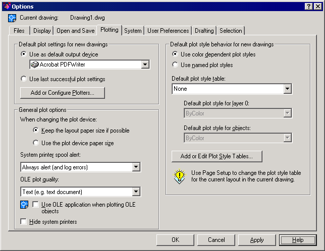
Under the Plotting Tab, you control
options related to plotting.
1 Under Default
Plot Settings For
New Drawings, you control default plotting settings for new drawings or
drawings created in AutoCAD Release 14 or earlier that have never been
saved in
Carlson
Survey 2000 format.
- Use As Default Output Device: Sets the default
output device for new
drawings and for drawings created in AutoCAD Release 14 or earlier that
have
never been saved in Carlson
Survey 2000 format. The list displays any plotter configuration files
(PC3) found in the plotter configuration search path and any system
printers
that are configured in the system.
- Use Last Successful Plot Settings: Sets the plotting
settings according to the
settings of the last successful plot.
- Add or Configure Plotters: Displays the Autodesk
Plotter Manager (a
Windows system window). You can add or configure a plotter with the
Autodesk
Plotter Manager.
2 Under General
Plot Options, you
control options that relate to the general plotting environment
including paper
size settings, system printer alert behavior, and OLE objects in an
Carlson Survey
drawing.
- Keep the Layout Paper Size If Possible: Uses the
paper size specified on the Layout
Settings tab in the Page Setup dialog box under the File menu as long
as the
selected output device can plot to this paper size. If the selected
output
device cannot plot to this paper size, the program displays a warning
message
and uses the paper size specified either in the plotter configuration
file
(PC3) or in the default system settings if the output device is a
system
printer. You can also set Keep the Layout Paper Size If Possible by
setting
PAPERUPDATE to 0.
- Use the Plot Device Paper Size: Uses the paper size
specified either in the
plotter configuration file (PC3) or in the default system settings if
the
output device is a system printer. You can also set Use the Plot Device
Paper
Size by setting PAPERUPDATE to 1.
- System Printer Spool Alert: Determines whether to
alert you if the
plotted drawing is spooled through a system printer because of an input
or
output port conflict.
- Always Alert (And Log Errors): Alerts you
and always logs an error when the plotted drawing spools through a
system
printer.
- Alert First Time Only (And Log Errors):
Alerts you once and always logs an error when the plotted drawing
spools
through a system printer.
- Never Alert (And Log First Error): Never
alerts you and logs only the first error when the plotted drawing
spools
through a system printer.
- Never Alert (Do Not Log Errors): Never
alerts you or logs an error when the plotted drawing spools through a
system
printer.
- OLE Plot Quality: Determines the quality of plotted
OLE
objects. The values are Line Art, Text, Graphics, Photograph, and High
Quality
Photograph.
- Use OLE Application When Plotting OLE Objects: Launches the application used to create the
OLE object when plotting a drawing with OLE objects. You can use this
option if
you want to optimize the quality of plotted OLE objects. This setting
is saved
in the drawing. You can also control this option by using the
OLESTARTUP system
variable.
- Hide System Printer: Controls whether Windows system
printers are
displayed in the Plot and Page Setup dialog boxes under the File menu.
This
option hides standard Windows system printers only. You can
control the size of the list of devices in the Plot and
Page Setup dialog boxes by moving a device's PC3 file out of the
Plotters
directory and its subdirectories.
3 Under Default
Plot Style
Behavior, you control options related to plot style behavior in all
drawings.
Changing the default plot style behavior using the Options dialog box
does not
affect the current drawing. A plot style is a collection of property
settings
defined in a plot style table and applied when the drawing is plotted.
The
default setting is Use Color Dependent Plot Styles. The plot style list
on the
Object Properties toolbar is disabled by default. You enable the list
after you
select the Use Named Plot Styles option and open a new drawing. You can
also
control Default Plot Style Behavior by using the PSTYLEPOLICY system
variable.
- Use Color Dependent Plot Styles: Uses
color-dependent plot styles in both new
drawings and drawings created in earlier versions of Autodesk products.
Color-dependent plot styles use the numbers from the color index to
create a
plot style table with a .ctb file extension. Each color is defined by a
name or
number ranging from 1 to 255. You can assign each color number to a
different
pen on a pen plotter to achieve different property settings in the
plotted
drawing. If this option is selected, a plot style is created for each
color
setting. You can also control Use Color Dependent Plot Styles by
setting the
PSTYLEPOLICY system variable to 1.
If you want to change the default plot style
behavior for
a drawing, select this option or Use Named Plot Styles before opening
or
creating a drawing. Changing the default plot style behavior using the
Options
dialog box affects only new drawings or drawings created in an earlier
release
of an Autodesk product that have never been saved in Carlson Survey
2000 format. This
setting is saved with the drawing. Once a drawing is saved with Use
Color
Dependent Plot Styles as the default, you can change the default to Use
Named
Plot Styles with a migration utility with a migration utility. However,
once a
drawing is saved with Use Named Plot Styles as the default, you cannot
change
it to Use Color Dependent Plot Styles.
- Use Named Plot Styles: Uses named plot styles in
both new drawings
and drawings created in earlier versions of Autodesk products. Carlson
Survey
plots the drawing according to the property settings you specify in the
plot
style definition. The plot style is defined in the plot style table
attached to
the layout or viewport. Named plot style tables are files with the file
extension .stb. You can also control Use Named Plot Styles by setting
the
PSTYLEPOLICY system variable to 0.
If you want to change the default plot style
behavior for
a drawing, select this option or Use Color Dependent Plot Styles before
opening
or creating a drawing. Changing the default plot style behavior using
the
Options dialog box affects only new drawings or drawings created in an
earlier
release of an Autodesk product that have never been saved in Carlson
Survey
2000 format. This setting is saved with the drawing. Once a drawing is
saved
with Use Color Dependent Plot Styles as the default, you can change the
default
to Use Named Plot Styles with a migration utility. However, once a
drawing is
saved with Use Named Plot Styles as the default, you cannot change it
to Use
Color Dependent Plot Styles.
- Default Plot Style Table: Specifies the default plot
style table to
attach to new drawings. A plot style table is a file with a .ctb or an
.stb
extension that includes and defines plot styles. If you are using
color-dependent plot styles, this option lists all color dependent plot
style
tables found in the search path as well as the value of None. If you
are using
named plot styles, this option lists all named plot styles tables.
- Default Plot Style for Layer 0: Sets the default
plot style for Layer 0 for
new drawings or drawings created with earlier releases of an Autodesk
product
that have never been saved in Carlson
Survey 2000 format. The list displays the default value Normal and
alphabetically displays any plot styles defined in the currently loaded
plot
style table.
- Default Plot Style for Objects: Sets the default
plot style that is assigned
when you create new objects. The list displays a BYLAYER, BYBLOCK, and
Normal
style, and it alphabetically displays any plot styles defined in the
currently
loaded plot style table.
- Add or Edit Plot Style Tables: Displays the Autodesk
Plot Style Table
Manager (a Windows Explorer window). You can create or edit plot style
tables
with the Autodesk Plot Style Table Manager.
System Tab
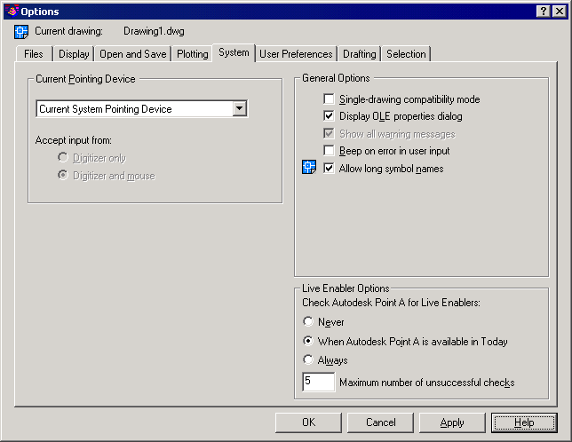
Under the System Tab, you control Carlson Survey system
settings.
1 Under Current
Pointing Device,
you control options that relate to the pointing device. This
field displays a list of the available
pointing device drivers.
- Current System Pointing Device: Sets the
system pointing device as current.
- Wintab Compatible Digitizer: Sets the
Wintab Compatible Digitizer as current.
- Accept Input From: Specifies whether the program
accepts input
from both a mouse and a digitizer or ignores mouse input when a
digitizer is
set.
2 Under General
Options, you
control general options that relate to system settings.
- Single-Drawing Compatibility Mode: Specifies whether
a single-drawing interface
(SDI) or a multi-drawing interface (MDI) is enabled. If you select this
option,
Carlson
Survey opens only one drawing at a time. If you clear this option, the
program can open multiple drawings at once.
- Display OLE Properties Dialog: Controls the display
of the OLE Properties
dialog box when inserting OLE objects into a drawing.
- Show All Warning Messages: Displays all dialog boxes
that include a
Don't Display This Warning Again option. All dialog boxes with warning
options
are displayed regardless of previous settings specific to each dialog
box.
- Beep on Error in User Input: Specifies whether the
program should sound
an alarm beep when it detects an invalid entry.
- Allow Long Symbol Names: Determines whether long
symbol names are
enabled. Named objects can include up to 255 characters. Names can
include
letters, numbers, blank spaces, and any special character not used by
Windows
and Carlson
Survey for other purposes. When this option is enabled, long names can
be used for layers, dimension styles, blocks, linetypes, text styles,
layouts,
UCS names, views, and viewport configurations. This option is saved in
the
drawing.
3 Under Live
Enabler Options, you
specify how Carlson
Survey checks for Object Enablers. Using Object Enablers, you can
display and use custom objects in Carlson
Survey drawings even when the ObjectARX application that created them
is
unavailable.
- Never: Prevents the program from checking for Object Enablers regardless of
your settings in the Today window.
- When Autodesk Point A is Available in Today: Carlson
Survey checks for Object Enablers only if Autodesk Point A is open in
the Today window. It is not necessary for the Today window to be open.
However,
the program checks for Object Enablers only if a live Internet
connection is
present.
- Always: Carlson
Survey always checks for Object Enablers regardless of your settings in
the Today window.
- Maximum Number of Unsuccessful Checks: Specifies the
number of times Carlson Survey
will continue to check for Object Enablers after unsuccessful attempts.
User Preferences Tab
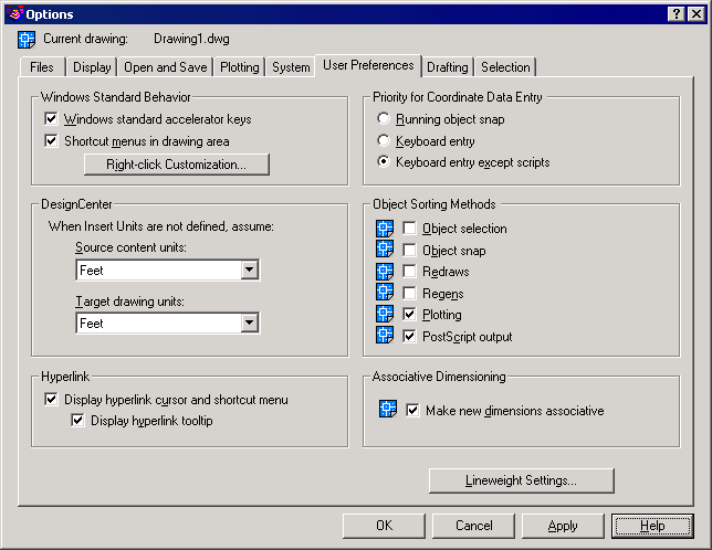
Under the User Preferences Tab, you control options
that optimize
the way you work in Carlson
Survey.
1 Under Windows
Standard Behavior
you specify whether Windows behavior is applied when working in Carlson
Survey.
- Windows Standard Accelerator Keys: Follows Windows
standards in interpreting
keyboard accelerators (for example, CTRL+C equals COPYCLIP). If this
option is
cleared, the program interprets keyboard accelerators by using Carlson
Survey
standards rather than Windows standards (for example, CTRL+C equals
Cancel,
CTRL+V toggles among the viewports).
- Shortcut Menus in Drawing Area: Controls whether
right-clicking in the
drawing area displays a shortcut menu or issues ENTER.
- Right-Click Customization: Displays the Right-Click
Customization dialog
box. You can also set Shortcut Menus in Drawing Area and the
right-click
customization settings by using the SHORTCUTMENU system variable.
2 DesignCenter
– this section
does not apply to Carlson
Survey.
3 Under
Hyperlink, you control
settings that relate to the display properties of hyperlinks.
- Display Hyperlink Cursor and Shortcut Menu: Controls
the display of the hyperlink cursor
and shortcut menu. The hyperlink cursor appears alongside the
crosshairs
whenever the pointing device moves over an object that contains a
hyperlink.
The hyperlink shortcut menu provides additional options when you select
an
object that contains a hyperlink and then right-click in the drawing
area. If
this option is cleared, the hyperlink cursor is never displayed and the
Hyperlink option on shortcut menus is not available (if shortcut menus
are
enabled).
- Display Hyperlink Tooltip: Controls the display of
the Hyperlink
tooltip. If this option is selected, a hyperlink tooltip is displayed
when the
pointing device moves over an object that contains a hyperlink. Display
Hyperlink Cursor and Shortcut Menu must be selected to enable this
option
4 Under Priority for Coordinate
Data Entry, you control how Carlson
Survey responds to input of coordinate data.
- Running Object Snap: Specifies that running object
snaps override
coordinate entry at all times. You can also set OSNAPCOORD to 0 to
enable
Running Object Snap.
- Keyboard Entry: Specifies that coordinate entry
overrides running object snaps at
all times. You can also set OSNAPCOORD to 1 to enable Keyboard Entry.
- Keyboard Entry Except Scripts: Specifies that
coordinate entry overrides
running object snaps, except in scripts. You can also set OSNAPCOORD to
2 to
enable Keyboard Entry Except Scripts.
5 Under Object
Sorting Methods,
you determine the sort order of objects.
- Object Selection: Controls how objects are sorted
during
selection. If this option is selected, Carlson
Survey sorts objects available for selection from those created first
to
those created last. If two overlapping objects are chosen during object
selection, the program recognizes the newest object as the selected
object. If
this option is cleared, object selection is determined by a random sort
order.
This setting is saved in the drawing.
- Object Snap: Controls how objects are sorted when
using Object Snap. If this
option is selected, Carlson
Survey sorts objects available for selection from those created first
to
those created last. If two overlapping objects are chosen when using
Object
Snap, the program recognizes the newest object as the object to snap
to. If
this option is cleared, Object Snap is determined by a random sort
order. This
setting is saved in the drawing.
- Redraws: Controls how objects are sorted when using the REDRAW command. If this
option is selected, the program sorts and redraws objects in the
drawing from
those created first to those created last. If this option is cleared,
the
redrawing of objects is determined by a random sort order. This setting
is
saved in the drawing.
- Regens: Controls how objects are sorted when using the REGEN command. If this
option is selected, the program sorts and regenerates objects in the
drawing
from those created first to those created last. If this option is
cleared, the
regeneration of objects is determined by a random sort order. This
setting is
saved in the drawing.
- Plotting: Controls how objects are sorted during
plotting. If this option
is selected, the program sorts and plots objects in the drawing from
those
created first to those created last. If this option is cleared, the
plotting of
objects is determined by a random sort order. This setting is saved in
the
drawing.
- PostScript Output: Controls how objects are sorted
in
PostScript output. If this option is selected, the program sorts and
exports
objects in the drawing from those created first to those created last.
If this
option is cleared, the exporting of objects is determined by a random
sort
order. This setting is saved in the drawing.
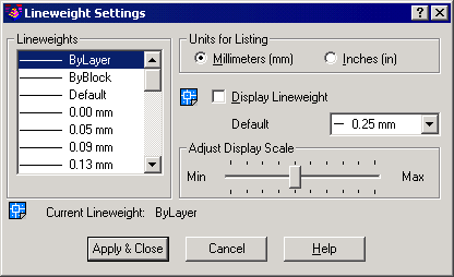
- Lineweight Settings: Displays the Lineweight
Settings dialog box.
Use this dialog box to set lineweight options, such as display
properties and
defaults, and also to set the current lineweight.
6 Associative
Dimensioning – this
section does not apply to Carlson
Survey.
7 Lineweight
Settings - Displays
the Lineweight Settings dialog box. Use this dialog box to set
lineweight
options, such as display properties and defaults, and also to set the
current
lineweight.
Drafting Tab
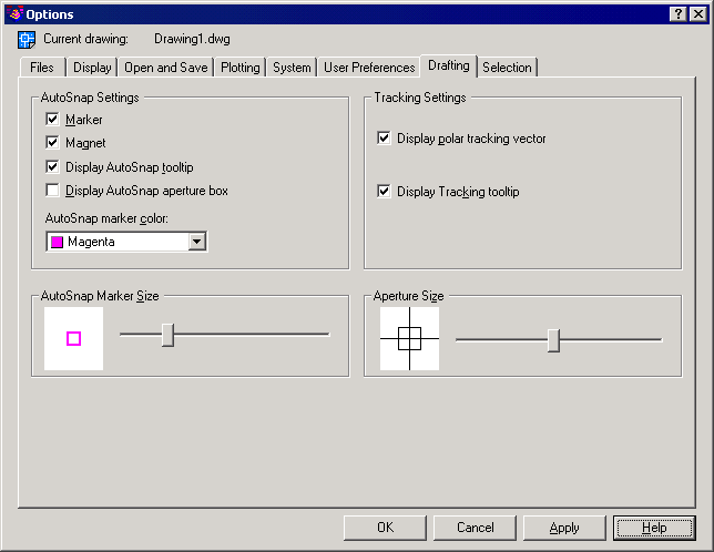
Under the Drafting Tab, you specify a number of general
editing
options.
1 Under
AutoSnap Settings, you
control settings that relate to object snaps. Using object snaps, you
can
locate exact points and planes including endpoints, midpoints, centers,
nodes,
quadrants, intersections, insertion points, and perpendicular and
tangent
planes.
- Marker: Controls the display of the AutoSnap™ marker. The marker is a geometric
symbol that displays the object snap location when the crosshairs move
over a
snap point on an object. You can also enable the Marker by setting
AUTOSNAP to
1.
- Magnet: Sets the AutoSnap magnet on or off. The magnet is an automatic movement
of the crosshairs that locks the crosshairs onto the nearest snap
point. You
can also enable the Magnet by setting AUTOSNAP to 4.
- Display AutoSnap Tooltip: Controls the display of
the AutoSnap
tooltip. The tooltip is a text flag that describes which part of the
object you
are snapping to. You can turn object snaps on and off from the Object
Snap tab
in the Drafting Settings dialog box. You can also enable the Display
AutoSnap
tooltip option by setting AUTOSNAP to 2.
- Display AutoSnap Aperture Box: Controls the display
of the AutoSnap
aperture box. The aperture box is a box that appears inside the
crosshairs when
you snap to an object. You can also set the Display AutoSnap Aperture
Box by
using the APBOX system variable.
- AutoSnap Marker Color: Specifies the color of the
AutoSnap marker.
2 Under
AutoSnap Marker Size, you
set the display size for the AutoSnap marker. Values range from 1 to 20
pixels.
3 Under
Tracking Settings, you
control the settings that relate to tracking behavior.
- Display Polar Tracking Vector: Sets polar tracking
behavior on or off. With
polar tracking, you can draw lines along angles relative to a drawing
command
From or To point. Polar angles are 90-degree divisors, such as 45, 30,
and 15
degrees.
- Display AutoTrack Tooltip: Controls the display of
the AutoTrack
tooltip. The tooltip is a text flag that displays the tracking
coordinates. You
can turn Object Snap Tracking on and off on the Object Snap tab in the
Drafting
Settings dialog box. You can also enable the AutoTrack tooltip by
setting
AUTOSNAP to 32.
4 Under
Aperture Size, you set
the display size for the Autosnap aperture. When Display AutoSnap
Aperture Box
is selected (or when APBOX is set to 1), the aperture box is displayed
in the
center of the crosshairs when you snap to an object. The size of the
aperture
determines how close to a snap point you can be before the magnet locks
the aperture
box to the snap point. The smaller the aperture, the closer you must be
to the
snap point to activate the magnet. Values range from 1 to 50 pixels.
You can
also set Aperture Size by using the APERTURE system variable.
Selection Tab
Under the Selection Tab, you control settings that
relate to
object selection methods.
1 Under
Selection Modes, you
determine the methods of selecting objects.
- Noun/Verb Selection: Allows you to select an object
before
starting a command. The command affects the previously selected object
or
objects. You can also set this option by using the PICKFIRST system
variable.
- You can use many editing and inquiry commands
with noun/verb selection, including: ALIGN, DVIEW, PROPERTIES, ARRAY, ERASE, ROTATE, BLOCK, EXPLODE, SCALE,
CHANGE, LIST, STRETCH, CHPROP, MIRROR, WBLOCK, COPY, and MOVE.
- Use Shift to Add to Selection: Adds or removes an
object to the selection set
when you press SHIFT and select an object. To clear a selection set
quickly,
draw a selection window in a blank area of the drawing. You can also
set this
option by using the PICKADD system variable.
- Press and Drag: Draws a selection window by
selecting a point and dragging the
pointing device to a second point. If this option is not selected, you
can draw
a selection window by selecting two separate points with the pointing
device.
You can also set this option by using the PICKDRAG system variable.
- Implied Windowing: Initiates the drawing of a
selection window
when you select a point outside an object. Drawing the selection window from left to right selects objects inside
the window's boundaries. Drawing from right to left selects objects
within and
crossing the window's boundaries. You can also set this option by using
the
PICKAUTO system variable.
- Object Grouping: Selects all objects in a group when
you
select one object in that group. With GROUP you can create and name a
set of
objects for selection. You can also set this option by setting the
PICKSTYLE
system variable to 1.
- Associative Hatch: Determines which objects are
selected when
you select an associative hatch. If this option is selected, boundary
objects
are also selected when you select an associative hatch. You can also
set this
option by setting the PICKSTYLE system variable to 2.
2 Under Pickbox
Size, you control
the display size of the Carlson
Survey pickbox. The pickbox is the object selection tool that appears
in
editing commands. The default size is set to 3 pixels; values range
from 0 to
20. You can also set the Pickbox Size by using the PICKBOX system
variable. If
you use the command line to set Pickbox Size, values range from 0 to
32767.
3 Under Grips,
you control the
settings that relate to grips. Grips are small squares displayed
on an object after it has been
selected.
- Enable Grips: Controls whether grips are displayed
on an object after you
select it. You can edit an object with grips by selecting a grip and
using the
shortcut menu. Enabling grips in a drawing significantly affects
performance.
Clear this option to optimize performance.
- Enable Grips within Blocks: Controls how grips are
displayed on a block
after you select it. If this option is selected, Carlson Survey
displays all grips
for each object in the block. If this option is cleared, the program
displays
one grip located at the insertion point of the block. You can edit an
object
with grips by selecting a grip and using the shortcut menu.
- Unselected Grip Color: Determines the color of an
unselected grip.
If you choose Other from the color list, Carlson
Survey displays the Select Color dialog box. the program displays an
unselected grip as the outline of a small square. You can also set
Unselected
Grip Color by using the GRIPCOLOR system variable.
- Selected Grip Color: Determines the color of a
selected grip. If
you choose Other from the color list, Carlson
Survey displays the Select Color dialog box. The program displays a
selected grip as a filled small square. You can also set Selected Grip
Color by
using the GRIPHOT system variable.
4 Under Grip
Size, you control
the display size of grips. The default size is set to 3 pixels; values
range
from 1 to 20. You can also set the Grip Size by using the GRIPSIZE
system
variable. If you use the command line to set Grip Size, values range
from 1 to
255.
Menu Location: Settings
Keyboard
Command: PREFERENCES
Prerequisite:
None