This command creates a sewer profile (.PRO) file with manholes, or
will
create a pipe profile (no manholes, no manhole width), and draws it on
the
screen. It requires that a grid is already drawn. It begins with the
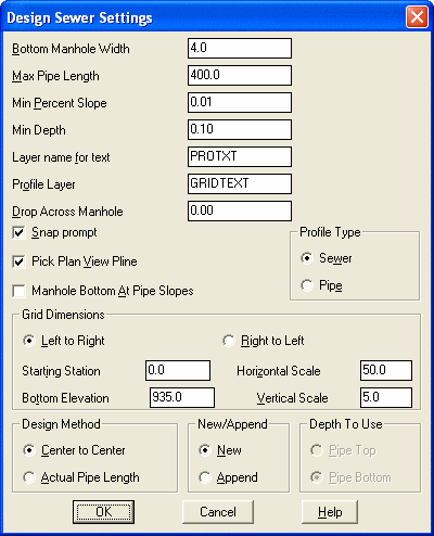
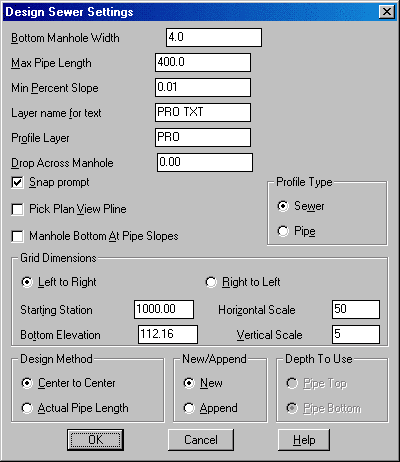
Desgn Sewer Settings dialog box.
Bottom Manhole Width: Specify the size for the bottom of
manholes.
Not available when Profile Type is set to pipe.
Max Pipe Length: Specify the maximum limit for the distance
between
manholes.
Min Percent Slope: Specify the minimum slope (absolute value)
between
manholes.
Layer name for text: Specify the layer name for annotation. If
you enter a layer that does not exist, it will be created.
Profile Layer: Specify the layer name for pipes and manholes.
If you enter a layer that does not exist, it will be created.
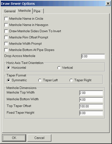
Drop Across Manhole: Specify the amount the elevation drop
across
the manhole in the direction of the profile. Will accept a negative a
value. Not available when Profile Type is set to pipe.
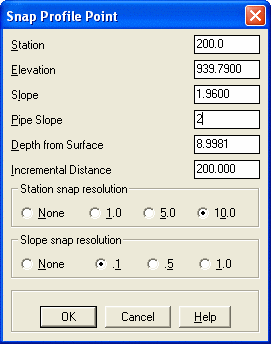
Snap Prompt: Activates the PVI Snap dialog box. See below for
description.
Pick Plan View Polyline: Allows you to select a polyline from
plan
view that represents the sewer centerline. This leads to the
plotting
of manhole symbols on the plan view and also creates default
manhole-to-manhole
stations.
Manhole Bottom At Pipe Slopes: When checked, the manhole bottom
will be drawn level with the pipe slope.
Profile Type: Choose between Sewer profile or Pipe profile. Pipe
profile do not include manholes.
Grid Dimensions: Specify the grid dimensions on which the sewer
will be designed.
Design Method: Choose whether distances specified are center or
manhole to center of manhole or actual pipe length. Not available when
Profile Type is set to pipe.
New/Append: Choose between creating a new profile (.PRO) file or
appending an existing file.
Depth to Use: Choose between specifying pipe top or pipe bottom
elevations. Not available when Profile Type is set to sewer.
File Selection dialog
Choose
a new profile file name to create.
Pick Lower Left Grid Corner <5000.0,5000.0>[endp on]: pick
the corner
Select existing ground polyline or ENTER for none: You may
optionally pick a polyline to use for calculating the depth from the
surface
as the sewer stations are entered.
Enter station or pick a point (Enter to End): 0
Depth from Surface/<Elevation of manhole>: 935.7
Enter the step up/down in feet <0.00>: press Enter
Station of second MH or pick point (U,E,D,Help): pick a point
If the Pick Plan View Polyline option has been chosen, the program will default to the station of the next vertex in the selected polyline. If the Prompt for Snap option was selected in the main dialog, then the Snap Profile Point dialog appears here. The station and slope may be changed to the nearest snap value. The elevation is the free variable and it will change to compensate for any snap. To change the elevation, select the elevation edit box and enter the new value.
Enter the step up/down in feet <0.00>: press Enter Enter
0.1 if pipe drops one tenth
into manhole and you are designing in
upstream
direction.
If you enter a station for the next manhole rather than picking a point
on the screen, then you will be prompted as follows:
Depth/Percent grade/Min grade/<Elevation of manhole>: 939.79
Size of pipe in inches <10.0>: 8.0
Station of next manhole or pick a point (U,E,D,Help): press
Enter
If you picked a plan view polyline, you will be asked:
Draw manholes on centerline [Yes/<No>]? Y Then
you will be prompted for the default manhole symbol to use.
Profile Sewer Settings dialog
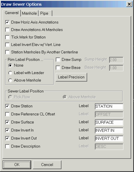
Sewer Label Options dialog
Sewer Annotation Options dialog (Displayed by pressing the
Annotation
Options button.)
Select existing ground polyline: pick a polyline or
press
Enter
to be prompted for each manhole surface elevation This prompt
only
appears if no ground polyline was selected above.
Manhole No. 1 label [MH #1]: press Enter
Manhole No. 2 label [MH #2]: press Enter
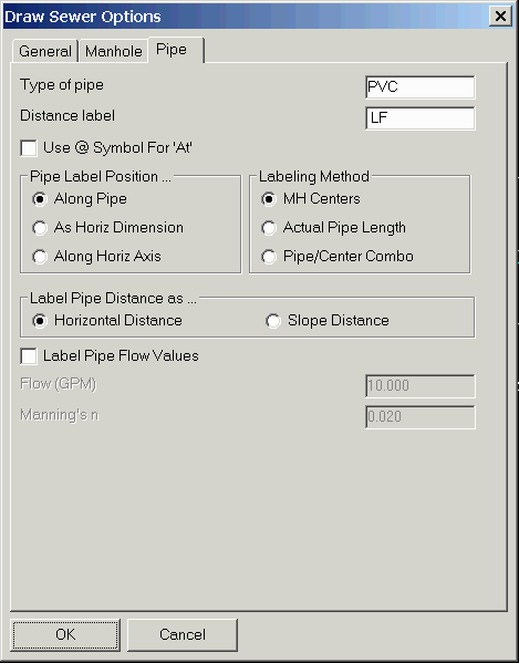
 |
| Pipe/Center Combo Labeling
Method
calculates the slope as the elevation difference from the edge of the pipe, divided by the distance between the manhole centers. |
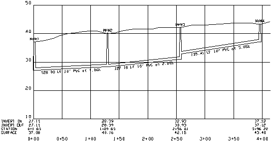 |
| Example of sewer profile and surface profile |
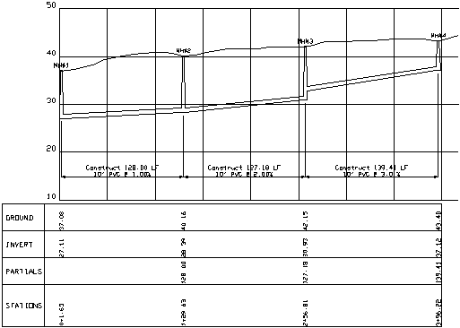 |
| Example of sewer profile using Horizontal Axis Text Orientation as Vertical and Pipe Label Position as Horizontal Dimension |
 |
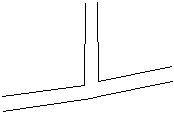
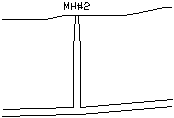
| Detail of manhole bottom at pipe slope |
|
|
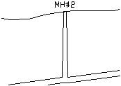
| Detail of drop across manhole of 0.2 |
|
|
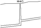
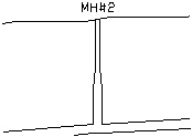
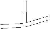
| Detail of step up |
|
|
| Top=2, Bottom=4, Offset=100 |
|
|
| Top=4, Bottom=4 |
|
|
| Top=2, Bottom=4, Offset=4, Fixed=0 |
|
|
| Top=2, Bottom=4, Offset=4, Fixed=2 |
|
|
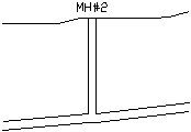
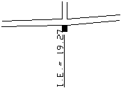
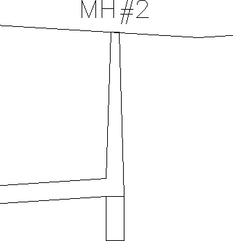
| Detail of Draw Manhole Base and Label Invert Elevation with Vertical Line |
|
|
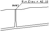
| Detail of Label Rim Elevation at Manhole |
 |
| Manhole with the Draw Sump option |
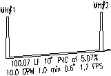 |
| Label Pipe Flow Values option shows flow rate, travel time, depth and velocity |
Pulldown Menu Location: Profiles
Keyboard Command: sewer
Prerequisite: A profile grid
File Names: \lsp\mksewer.lsp, \lsp\profedit.arx, \lsp\profile.dcl